Project 2. Full restoration of an AVO Mk4 tube tester
I have seen this so often before... A very good tube tester from my friend... he needs to sell it.. etc. This one was in that category, and I was offered it by a person who I know a long time. As received the tester, I did a quick check on the main functions, and all was ok, apart from a jittering back-off potentiometer, but that is normally something minor. Just the precision was not so excellent, but I thought to calibrate it another time. I have collected many tube testers over the years, and I had this one on the shelf a few years, with some other AVO's.Now, I was ready to give it a good check up, and then I found out it needed more attention than I thought. Mind you this tester was sold to me in good trust it was all ok, and myself I did not notice any problems while quickly checking it. I would say, many users would gladly would have used it in the original condition, and be fully satisfied. Yet I checked it systematically, which begins with removing the meter, and check this as a separate. Then it came to the surface, the meter was out if specs, and some strange calibration was done to get the tester sort of working as good as possible anyway. However this is impossible, since a near-perfect meter is an absolute "must" to get perfect accuracy. That explained the low accuracy the tester had overall.
Here is how it went. Please take some time to read it, as you can see for me this is something I like to work on very much. Also you will understand after reading it, what it really takes to get such a complicated tube tester back to 100% condition again.
Now the tester is finished, it has the same precision as the Amplitrex AT1000 testers I have here, but the AVO has higher resolution for some of the parameters, such as grid voltage.
You may find it perhaps amazing, some will not believe, this 50 years old tester can outdo the Amplitrex new digital tester. Myself I know this is so, and I will prove it here, with test reports, for this particular tester. The Mk4 can be excellent precision, but really only when there is no off-specs resistor inside, when the meter is really perfect, when nobody has been jerking with the factory calibration, and when the user calibration underneath the side panel is done with experience and a good reference tube. Then, and only then, the AVO is mint condition, and resolution is much higher than the Amplitrex. All other AVO's ("unchecked", "probably ok", "from my fathers shop") etc, they all need extensive service and repairs, and both the seller and the buyer do not know, and do not notice. Well perhaps the seller knew it, but often also not. Myself, I have never seen one that needed no maintenance. Yet, if done good, the tester will last for 20 years again, and is awfully precise!
 |
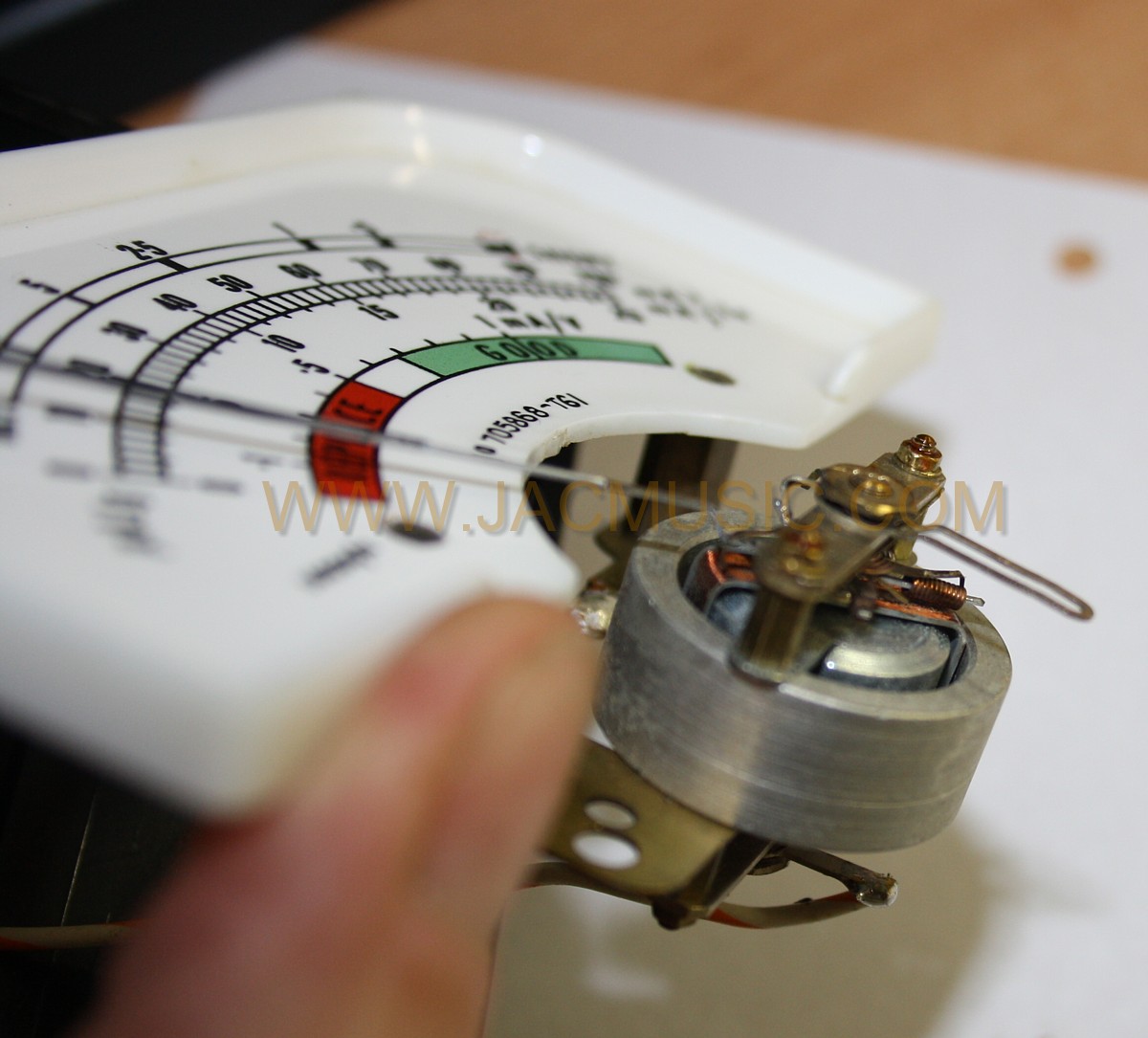
The mains calibration. That worked when I tried it before buying. I could get the meter on the calibration mark when I bought it. This time now, I measured the transformer voltage from the inside and it was set for 190..210V while the mains here is 235V. Yet the mains calibration pot meter was close to maximum. You are probably confused already now, but I realized the seller might have known this. Please learn from me, with tube testers, if you run into any problem "the seller may have known" you should interpret this as: "He must have known, and that's why he decided to sell the tester. (to you). My personal experience is, you have 95% chance on this, and the other 5% is for cases where a repair is easy to do. So most of the time I find the defective spot with unsuccessful repair attempts clearly visible. Well, then I know what I have to do, because usually I succeed to repair this, the tester is fine again. TEST: I adjusted the fuse board mains for the setting of 230...250V. Now, with 235Vmains as we had on that moment, I should be able to set the meter on the calibration mark with the "SET~" SWITCH, and with 235V it should be one of the last settings, clockwise. |
|---|---|
|
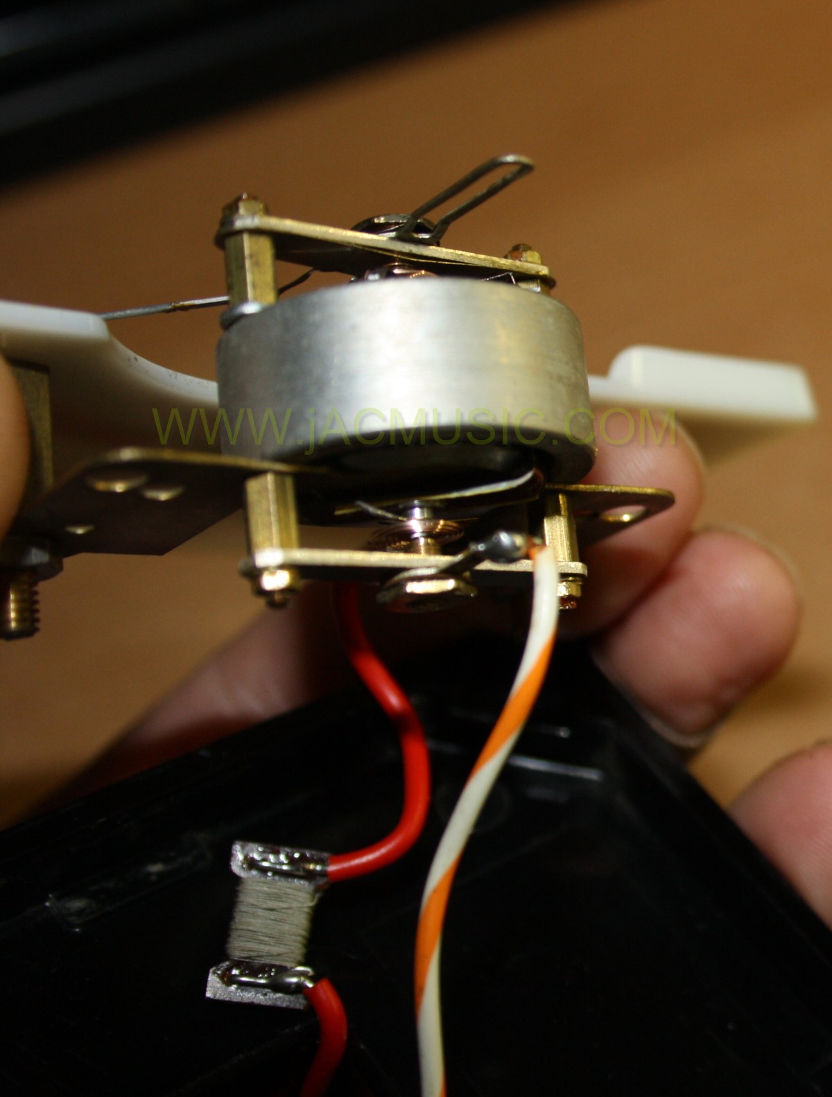
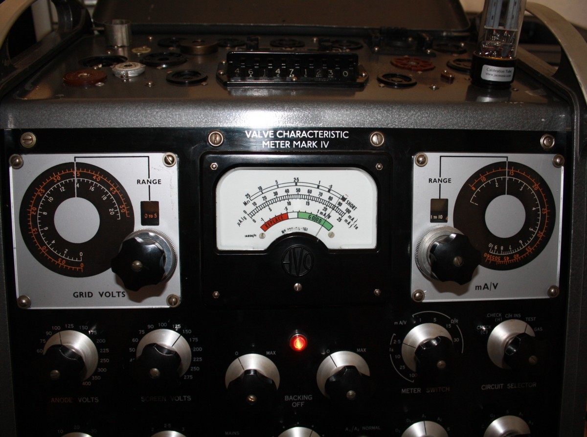
It didn't work. The calibration mark could not be reached with the SET~ switch now. I could only reach it I set it back to 190..210V. So what did this stinky seller do.... he just set the tester for 190..210, and that way, with 230V he could force the needle to the Calibration mark. Thus "fixing" the problem with the non-working mains calibration. Look at this picture. This is as far as I could get it, with the SET~ switch all to the right. This may mean, one of the three transformers are damaged, but I was lucky, they were still fine. Then I put in a calibrated Moving coil meter in series with the meter, and the problem got clear. The meter needed 35uA for a full scale, and it is a 30uA meter. An AVO is really only precise when all things are within tolerance, and there is no way to work around. So if a resistor is 10k+/- 2% there is no need to have a 1% resistor, but don't try it with 3% if you want the whole tester to be accurate. The most amazing thing is R36, which must be 200Ohm +/- 0.5%. I tried it, and adding in parallel a 20k resistor to R36 will reduce the meter reading with 5%. So for this resistor I am going to do a "zero" percent calibration. More about this later. R36 sets the internal impedance of the tester, and messing around by the previous owner with it was part of the dirty job by the seller of the tester. More about R36 later. Now at first, I assumed the meter magnetism must have gone down. With some meters there is a way to adjust this. So I opened the meter, and out came the reason for the 35uA full scale needed instead of 30uA. |
|
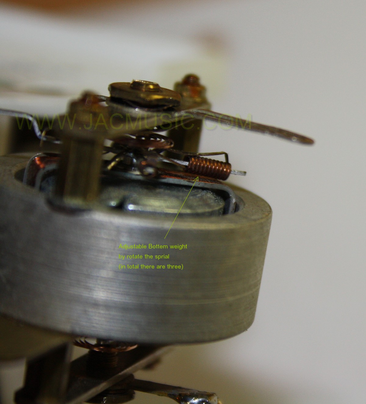
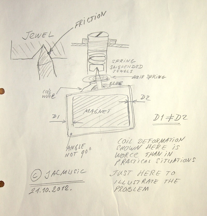
The whole inside was tweaked and changed in some attempts to increase the sensitivity. Unfortunately things don't work that way, and he gave up on it, leaving behind the meter as is. To get the tester "repaired" still, the seller just set the tester to 190..210V, and of course now at 230V you can reach the calibration mark easily. So that's what he did. Now all voltages inside were too high of course. He messed around with all other calibrations points inside, even messed with the factory calibration, that you are not supposed to touch. Somehow he managed to make the tester "acceptable", and ready for sales. That's when I bought it. The meter was damaged by over current. Other as what many think, this will not burn the coil. You can not burn a coil with 300uA, though this is 10x more current that normal. 300uA is not enough for developing any heat, but there will be another kind of damage at 300uA: This will violently hit the needle against the end of the scale, and this will deform the coil. Specially since (very often) the electrolytic meter protection capacitor has gone high impedance over the years. Such deformations can be seen easily seem under a strong lens, and fixed perfectly, since the coil is very soft, and becomes trapezoidal shape. This is really easy to correct , when the coil is removed. All it needs to be is a square shape again. However, it requires complete complete desoldering of the hairsprings, re-adjust the pivot jewels and re-build the whole meter in fact. It's not very difficult, but you can do things wrong very easy, and the meter is gone. Also one of the pivot jewels had jumped out. That is normal when the meter is badly unbalanced, the side fore on the jewels becomes too high. These are pretty large size, and can easily be removed. I took the opportunity to clean them also. The previous person put oil on them, but this is wrong. The oil will give capillary problems, and if adjusted well, there is no friction anyway, since a well balanced needle is suspended by the hair springs mainly. The jewels have almost no force on it, and no friction at all. Anyway, the attempt to oil them, tells me, he was aware of the friction. A badly balanced coil has side forces on the jewels, which depend on the angle, and this gives the infamous scale unlinearity, and friction. Mmmm it's really as easy as that, but you do need to practice a little bit on some old meters, that you would not need any more. The Ebay price of a new meter is 450 Euro (yes!). So better not damage your meter, and you can praise your tester when you have a perfect meter inside. |
 |
Balancing of the meter. If the coil is nicely in shape, it moves in the middle of the magnetic gap, regardless the rotation angle. This is elementray for good linearity, together with balancing of the needle for vertical operation. I was able to re-adjusted the coil's shape nicely symmetrical again, so original shape, and the meter is almost in balance again. Final balancing needs to be done still. First, without the circular pivot springs, you have to set the pressure force on the sapphires, such that friction is close to zero, yet the coil is stabile in place. This is a balancing act, you can only do without the pivot springs. So you need to find exactly that point where friction begins, and then re-adjust just that tiny fraction below it. The needle as you will see now has a small play, like approximately 0.2mm at the end of the needle tip. It's a little bit like a rattle, when you shake it. It's just this fraction of play you need, and this means the axis is caught by the jewels, but without pressure on it. Once the springs are in, the needle will be better fixed more tightly, since they give hold in all directions. (Not just circular, but vertical also) Next is to balance the needle, still without the hairsprings. In the upright position, it"fell over" to the right when it was above 70mA on the scale. It fell by itself to the end of the scale. It is interesting to see with how large force the needle falls over. It sort of really falls over. So unlinearity resulting is probably a lot. As you can understand, it is just THIS effect causing unlinearity. So if the meter is indicating " 70mA" on the scale correct, it would indicate "100mA" on a lot less than full scale. If the balance is good, you can tilt the meter forwards or backwards, and tap it, and the needle may not move, yet if you do move it by hand it has zero friction. So this is without the pivot springs. You out the needle in any RANDOM position, and then you hold the whole meter in and random position, and the needle will not move. Now is so, the meter is balanced. If done, very gently tape a construction on the scale of some thick paper, to hold the needle at zero, yet not bend the needle in any direction. Now, with the meter in the normal use position (for AVO Mk4 that is upright) solder the pivot springs back in. |
 |
Luckily the coil itself was in perfect condition still, because that I could not repair. Though I read a story in the internet about somebody fixing the coil of a Hickok. This AVO coil has even thinner wire. This balancing requires very good mathematical understanding, to get it done with three counterweights, each interfering with the other. Well after a lot of adjusting, it was done. I took the opportunity to remove some magnetic particles from the magnet, re-seal the glass, and add a dust catching tape inside. This tape is of a kind, I have personal excellent experience with, as I can say it will not loose it's "stick" after minimum 15 years with air exposure. How do I know? I had an old roll of double sided tape tape, in my drawers all of those years, and sticks still as new. (Compay called TESA) After final assembly this meter was a "dream" again! It works as perfect as new, and linearity is absolutely perfect. So with this meter, the mains calibration pot meter was within range again.
|
 |
I checked now the Ohms Meter function of this tester. It was excellent. I Just put back in the same picture here. The tester has a 50 Meg Ohms Meter, which is the outer scale. It is used when you set it on leakage. The scale stops at 25Megm but if you look carefully, you can estimate a 50 Megs reading. Normal multi meters work with a 9V battery, but this one here works with appr 220 Volt DC. Which you need indeed, because leakage, corona, creepage, all these things appear at high voltage and hot filaments. To test it, just connected a know resistor from the A1 link to the and A2 link, and on leakage "A1" and "A2" you must now measure this resistance value EXACTYLY. If not, you have more work to do. The highest precision resistor I have is 10 Megs. The needle comes exactly on "10". PERFECT. This proves many of the inside circuitry to be good now, including the meter. Though the meter has to be tested as a separated unit also. Conclusion: A quality panel meter is a work of technical art. Specially such sensitive ones as 30uA @ 3250 Ohms. Never try to "improve" a bad meter by adjusting the pivot jewels. They are factory adjusted with highest precision. They do not loose adjustment other than by coil damage. If you change something with the pivot screws, you change the position of the axis, and then the pivot springs develop a force in the direction along the axis, which gives friction. So the only thing is a full procedure as described here, or you make things worse. |
 |
Grid Voltage error (Repair) Now comes the grid voltage repair. With this setting, there is a small overlap with the settings wheel. So when the range is: 0 to 5 (+10) as picture here, you can set it from 10 to 15 Volt on the red scale. The next higher range is 0 to 5 (+15). so you can set it from15 to 20 Volt. TEST: You can set 15.0 Volt with either scale, and the reading on the panel meter must be fully identical. Also when you flip from the red to the white scale. Any differences can only come from the resistor divider network, the pot meter linearity, and the mounting of the dial wheel to the pot meter This mounting is a permanent factory calibration. It didn't work. Obviously the factory setting had been changed by the seller, the reason I found. One of the resistors in the divider network had been overheated and the paint was a bit burned. The seller discovered this as well, because this resistor had been cut loose with one end, to measure it. So did I, and it was 4% off, instead of maximum 1%. The seller just left it in. He must have seen the paint burn, but he must have thought 4% deviation was fine, not checking the tolerance from the manual. . Or not have a 1% ohms meter. Whatever the reason, he left the resistor in, and instead choose to screw around with the factory calibration. This is the position of the dial wheel on the potentiometer. I use this table I made myself to check it. I do the calibration with a scope, this is more precise as the procedure in the manual. Whatever your choice, if you use the Excel table, whatever setting on the "Grid Volt" is must produce this, and if not there is work to do. After this comes the calibration with the pot meters at the side. That is the user's calibration, not the factory calibration. Mind you, the previous owner has been screwing around with the factory calibration. |
 |
Here you see a black shrink sleeve, and inside is a selected array of metal foil resistors, which together have exactly the required value if 2500 Ohms +/- 1%. I think like this it looks nicely as original. All others resistors of the grid voltage switch were still excellent. So this is MOST likely how the meter got damaged, by a tube with a grid to cathode short circuit. You can discuss about it, if this is a tester's failure or an operator failure. Probably they skipped the "shorts" test. It is just this, what AVO is warning against. Anyway after replacing the resistor, it was more needed than before to do the factory calibration. The best way is by an oscilloscope, which is better as in the service manual. After checking another Mk4, that was never worked on, I found how to select the set points. It was kind of obvious. The service manual explains how to use a voltmeter instead, which is easier to do, but will not give the same nice result. After this was done, the Vg dial performed EXACTLY as expected. Now when I set 15V on two of the scales, the meter reading is identical. It was the wrong reading, but at least identical, and it was so for all (nine) scales like this. Another step forward :) |
REPAIR PART FINISHED - NOW COMES THE VERIFICATION This tester is so precise, it will outdo the Amplitrex AT1000 |
|
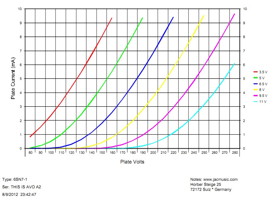 |
So now the tester is working good, and I wanted to see what it can do. These curves you see here are from a NOS 6SN7, taken with the Amplitrex AT1000 computer. As we will later see, the precision of this 60 years old AVO MK4 tester will outdo the Amplitrex, which is possible since the Amplitrex is not very high resolution. Yet, first now we need to see with the AVO where we are at all. The numbers underneath the vertical lines of the AT100 graphs correspond with the lines in an unusual way, as more things a bit unusual with the AT1000 tester. Anyway the values are taken correctly, but you need to get the numbers from the curves by penciling in the lines you need. I will replace these curves later by the Sofia curves, which I can directly read data from without having to estimate the test points, and besides the Sofia gives transconductance at any test points I choose. |
|
Verification of the results: So we are going to need the values at 150V, 200V and 250V, and check a few grid lines. You can click on the curve to see the details. As you can see, this AVO Tester reproduces the Amplitrex AT1000 values. What is interesting the grid voltage of the Amplitrex is given with less resolution as the AVO. The Amplitrex will jump from 3.5V to 3.6 (lack of resolution) whereas with the AVO you can at least estimate on the scale the distance between 3.5 and 3.6. So you can read 3.55 from the AVO scale. Plate =100V, -Ug=3.5V, Result 2.3 mA Conclusion: The tester is in perfect condition. I have been verifying it's function with the Amplitrex AT1000. Actually I really have come to the conclusion, it is better to verify the Amplitrex with a mint condition AVO Mk4. In some planned work, I am going to do so. Meaning I want to produce a really absolutely "known" tube, and pass it on to several testers. |
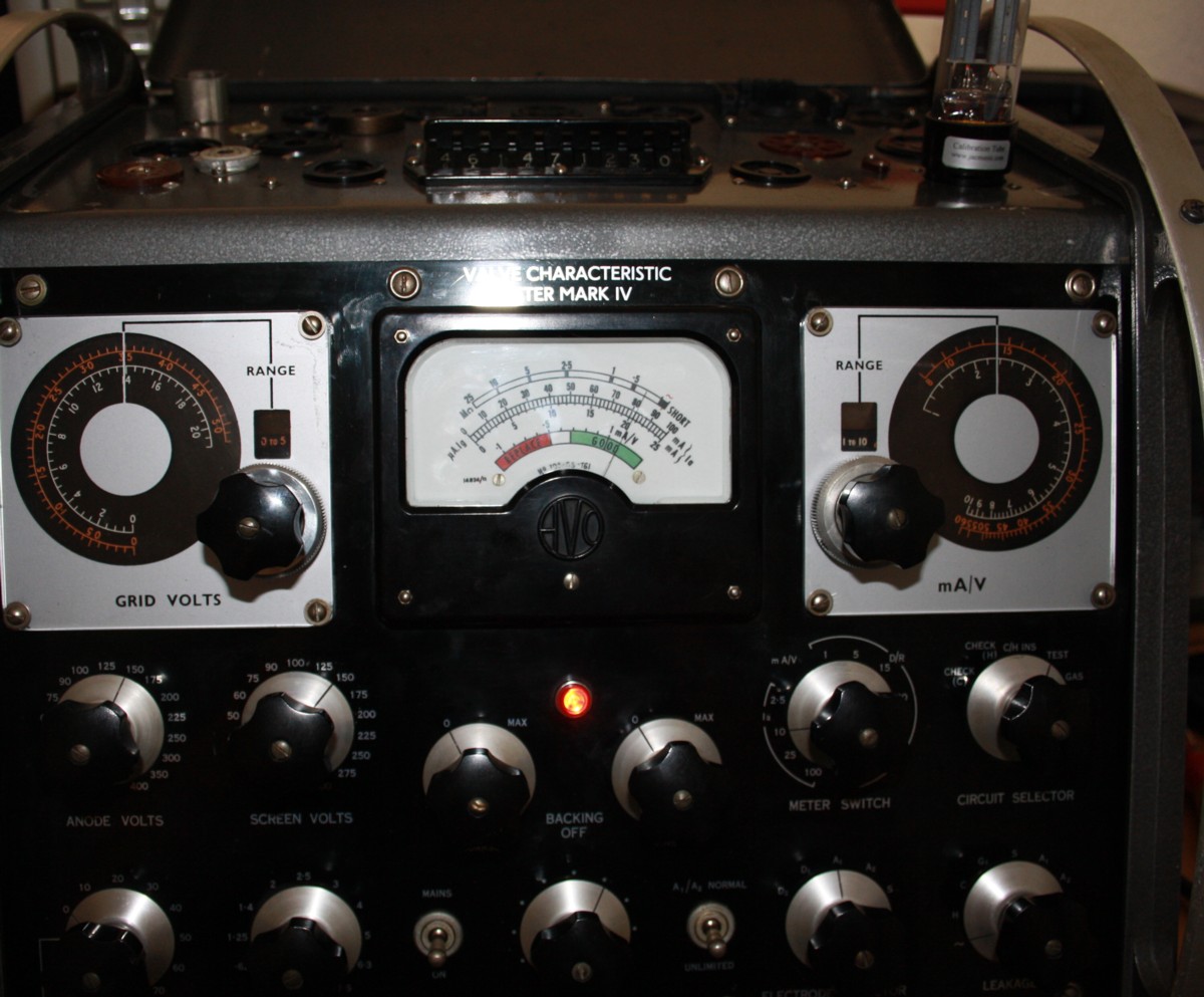
| Sorry for the not so nice picture quality, but they are made with a CANON EOS 1000 camera. | |

 |
 |
|
|---|---|---|
TO BE CONTINUED |
Work done:
-
Panel Meter cleaned from the inside and fully re-adjusted. Including pivot jewels removed and cleaned. Meter Coil re-centered, and meter needle re-balanced. Hair springs removed and re-adjusted, coil impedance and sensitivity set for exactly 3250 Ohms, 30uA. Magnet removed and freed from magnetic dust. Glass re-sealed. Add additional protection network on the meter outside, with Tantalum capacitor and 1 Ampere diodes. Inserted special dust catching tape inside the meter. The meter is the heart of all Mk4. This meter is a dream, and it is in mint condition now.
-
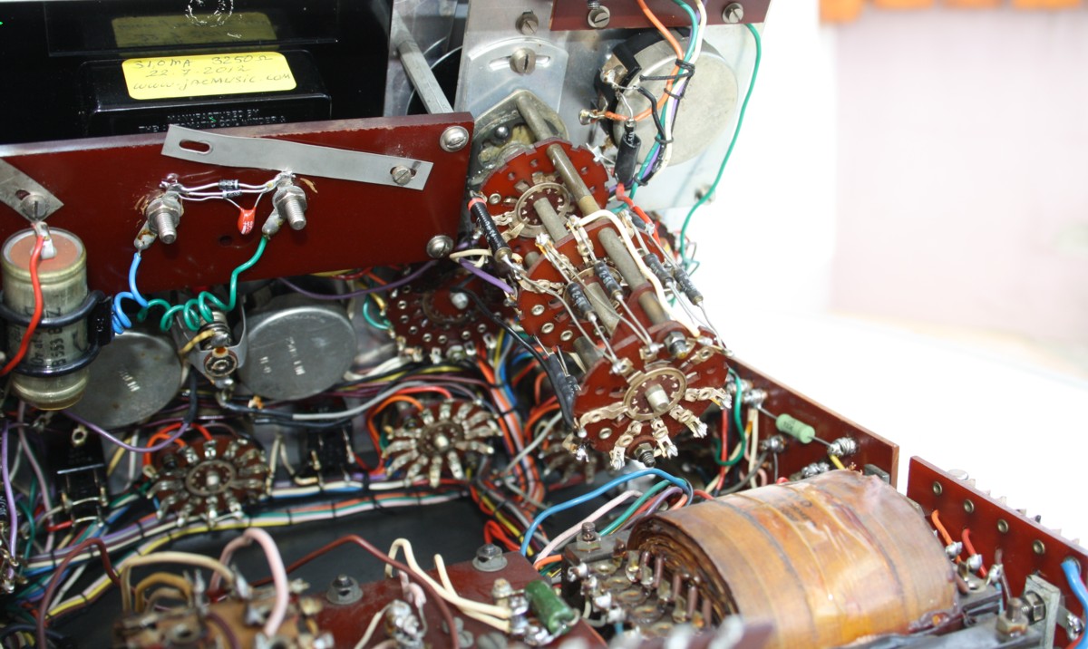
Tester cleaned from the inside. Checked and adjusted the overload relay. All switches cleaned.
-
Back off pot meter opened, cleaned and re-adjust the arm.
-
All power diodes replaced by new ones, just to be sure. The large 100k carbon resistors replaced by modern ones. They were 12% off, and their value is not critical. They can as well be 150k. Yet a 10% resistor with 12% off, means is a sign there is detoriation inside. So I replaced them.
-
All electronic parts inside visually inspected, and if possible tested without desoldering them. (For instance a resistor inside the circuit with a value of "200k 5% " printed in it, may not measure 220k regardless of the circuit attached to it. The circuit only makes the impedance lower. Also you can set switches such that the part gets disconnected at one end. Then function of many resistors is proven by correct scale switching, and/or correct signals inside. You end up with a few critical parts only that you need to solder off at one end, such as the meter calibration resistors that must be 2,96 Meg Ohms exactly.
-
Grid pot meter and Transconductance pot meter adjusted (this is the factory calibration, the setting of the scale wheels to the pot meter axis). All voltages checked in steps of 1Volt +/- 2%. Grid unit was completely removed, and mechanics cleaned and adjusted, to have it really work PER-FECT. One resistor of the unit was off specs, and replaced.
-
Plastic windows of dial wheels removed and machine polished. They are shiny like new.
-
User's Calibration was done with oscilloscope. (From the side panel).
-
Verified all functions. Ohms measurement, Plate current measurement, All leakage functions, Gas test, All plate and screen voltages, and a lot more.