Calibration of a Tektronix 5113 Oscilloscope
Ebay, here we go again
I had only the chance to buy it on Ebay. Well the price was not high, and three modules were with it. It was said to work very good, and not dead on arrival. Well it worked for a few hours, and then the CRT stopped. The High Voltage transformer was whistling badly, and I thought it was bad. I was lucky, it was only the first capacitor was shorted. At 10nF, 4kV these are a bit rare, but I found a replacement. The original was a disc type, which is sintered material. Frankly, at 3400V DC, such should not be used. Such "isolated" crystals inside, it's just asking for trouble. On the Tektronix forum, they already wrote, it's probably NOT the transformer, and they were right. So the replacement is a foil cap now.
After the HV was working again, it appeared the Channel chopper oscillator was dead. The lousy seller must have known it, because he removed the chopping blanking transistor. (Leave it in, and the screen blanks when you choose "chop" but there is no chopper frequency). So he nicely frauded this sale. This man was a school teacher in Holland. He was too stupid to find the cause of the failure, and so he sets up this fraud, to sells the scope "as is". Oh well, same as politicians are always lying.
But on the other hand, it is satisfactory to find out WHY the item was sold, if you can fix it nicely. Then chances on any other nasty problems are lower.
Disclaimer.
You will screw things up when changing the setting of your time base module experimentally, like learning by doing. It's not going to be like that, if one calibration depends on another first! In that case, you need the right order. So you can change the vertical amplifier sensitivity, but that provides you will not change the CRT high voltage after that. If you change the High Voltage (3400V) of the CRT tube, you need to re calibrate everything related to this, like horizontal and vertical amplifier sensitivity, focus, intensity, and whatever else is related. So just try to see what happens is not a good idea with the time base setting. Probably the easy to do settings were maintained already by previous owners. But the harder they are to do, the less chances are they were done at all. So now, after 50 years not calibrating the horizontal amplifier, and the time base module, it's time to do those harder settings now.
However this is no guaranteed guidance for how to do a calibration yourself. On the other hand, such calibrations of which most people know they should not touch it, like horizontal and vertical amplifiers, after 50 years are not really accurate any more. So going through some procedures with those, may pay off. The following is only I did this myself, bypassing the need of special calibration tools, and it is no calibration guide line in general.
Where I get my information from:
- Tekwiki for the documentation. (you can participate there, very friendly website owner)
- The Tek Scopes forum for when you want to discuss. This is one of the very few forums I have seen, where you get a normal answer from normal people. No dominant inmates there, disciplining the newcomers. Many retired Tek engineers there, soldering on their beloved items, being really helpful to others.
The use of a time mark generator.
The Tektronix manuals always write, take a time mark generator, take a voltage calibrator, and take a calibrated vertical module. Take this and that that.... But hey... I don't have all these items to "take".
So I thought, today's very accurate multi meters and universal signal generators should make it possible perhaps. I asked on the Tektronix forum if this is really needed, but they said that touching the time base calibration, without time mark generator, is something I would probably regret. I did find a work around however.
At first, I followed the Tektronix official calibration routine by the book, just to see what could be done without special tools, and to see where it gets stuck. Now there is some point in this routine, where I would say it's the chicken or the egg. They say "take a calibrated vertical module". And then, with that they adjust the vertical amplifier. Mind you, this is the official TEK procedure. This is no good way! The result of that calibration depends on how well this vertical amplifier module which you just "take", was calibrated. In my case: Not calibrated at all. My conclusion: Forget this. And I suppose this was what the guys in the forum were trying to tell me.
Here is how I did the calibration still
Equipment used:
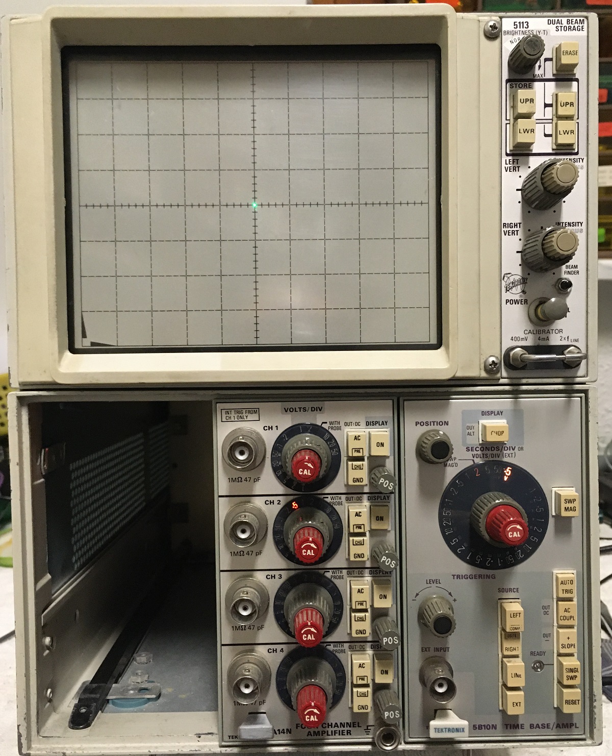
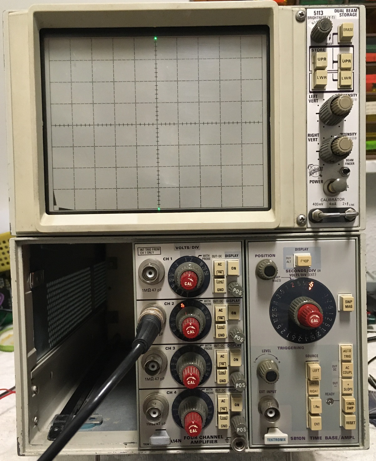
5113 Dual Beam, Dual Storage Oscilloscope
5A14N vertical module in slot #1.
5B10 Time base in slot #3
Agilent 34401A multi meter
Agilent 33120A Arbitrary Waveform Generator (= very versatile Oscillator)
If not calibrating the horizontal and vertical amplifiers first, you get a mess, when the time base is 5% too slow, and you would just set the horizontal amplifier 5% higher gain. Because that would also make the beam move faster.
So, calibrating these mainframe scopes, means the horizontal and vertical amplifiers have to be calibrated first, and after that, the time base module and vertical modules can be calibrated, using this scope, with now calibrated horizontal and vertical amplifiers. That is the whole principle.
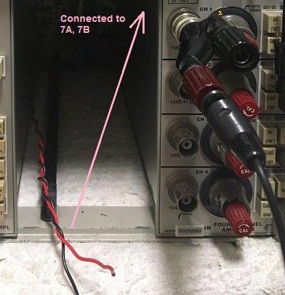
The sensitivity of the horizontal and vertical amplifiers is normalized at 50mV per division. This has to be set first, and directly like this. So no matter what the set up is, at 200mV at the green connectors inside the mainframe, the beam should move 4 divisions, both horizontal or vertical.
The question is, how to get this 200mV on the mainframe connector, so at the input of the horizontal and vertical amplifier? There are more ways for this, and in the TEK calibration instructions, they use a very difficult method, which needs of course again a time mark generator to "take" and a calibrator for the AC signals to "take".
I think when using an Agilent 33120A Arbitrary Waveform Generator, this is all we need, and frankly it works a lot faster, easier to understand, and with better result. I verified the output signals of the Agilent 33120A, with the Agilent 34401A multi meter, and both read exactly the same values and frequencies, with 4...5 digits precision, also at millivolt level.
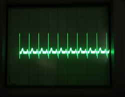
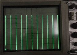
Another pretty nice reference is the internal calibrator of the scope itself. It is just there, and no long wires needed. This thing is locked to the mains frequency, and it gives a square wave of 2x the mains frequency. We have 100Hz here, which is more convenient than in 60Hz regions. So it gives a perfect 0.1 Second time definition. However it has no good 50% duty cycle, so it can only be used to display 0.1 second precisely, but not 0.05 second (for half a cycle). The amplitude is very accurate, provided the amplitude is calibrated. A problem with this is, the duty cycle is not symmetric. So you can not measure the RMS voltage to calibrate it.
To calibrate it, first measure exactly the duty cycle of it, use that as a correction factor, and then you can calibrate it with the Agilent 34401A multi meter, or any other which does RMS volt measurement accurate. So suppose, the signal is 46% high, and 54% low, you have to calibrate it for 184mV RMS. (400*0,46). That would give you indeed an precise calibration signal, because the 400mV is derived from the +30V which is a very stabile circuit. The Agilent 34401A multi meter can do this very good.
However there is no calibration potmeter for that, and the only way is to change the amplitude is change the +30V supply. The +30V has a very small tolerance, which I used to calibrate the scope calibrator output. So I set the +30V until I had exactly the required value, and the +30V was still within calibration. Then I set the -30V to the same level. So +30 and -30 are nicely balanced.
As a second test, after calibrating the vertical amplifier of the scope, this calibration signal must test exactly at 400mV peal value. If not, one of the two actions was done wrong. So you have a double check on the vertical amp calibration, and on your work.
First CRT geometry must be perfect. Forget touching the Horizontal and Vertical amplifier calibrations, if the CRT picture is unlinear or has distorted edges. Go by the book, and do repairs if needed. If you can't get the geometry right, do not touch the Horizontal and Vertical amplifier calibration. Luckily with my 5113 that worked out excellent. So I could just continue from there. Since the CRT tends to distort at 5 divisions a lot more than at 3 or 4 divisions, I preferred to take 4 divisions.
The calibration process
This process is not complete. It is only how I calibrated some parts.
Preparations.
- Set the mains power supply jumper to one of the three ranges, matching the actual mains voltage best. By default it is set wrong, from the 1970's when mains voltages were lower.
- To verify the high voltage 3400V at the back of the CRT tube, I made a series resistor, of appr 80 pcs 2M2 resistors in series, on a PCB, with two banana plugs on it. If put in series, this changes my 500V hand held multi meter into a 5kV Meter. The number if resistors needed, depends on the actual input impedance of the battery operated meter. You can NOT do this with a mains connected meter. Needless to say this set up was treated with greatest respect, and anything touched only with my right hand, and the left hand in my pocket. For switching the scope on and off, I had someone else do this for me. So I have really only one hand on the set up. Connect and hold the HV probe inside the test hole, BEFORE switching the scope on, and also do not pull it out with the scope on. This pulls an impressive long spark otherwise. So I say it carefully here, this high voltage output circuit can be deadly. A fatal accident needs somewhere from 10mA to 60mA which this transformer can probably not do at 3k4V, but the danger is current, not voltage. At lower voltage as would take place when you touch it, it might well be able to supply this current, and kill you. The output capacitors if charged at 3k4V, can easily supply a pulse in a much higher range. It is why I say here, this can only be done by a qualified high voltage technician.
- First adjust the +30V and -30V power supply, trace rotation and geometry correction, because that would give a calibration error otherwise. Also adjust the cutting off of the brightness adjustment knobs by the manual.
- For adjusting the +30V and -30V use the internal calibration signal, as explained in the text here. When that works within tolerance, leave those voltages as is. So do not try to get exactly 30.000V, as this is not necessary, and gives no benefit. Like this, you will have a very good calibrated 400mV signal, which is always convenient to have it quickly at hand.
- Write the actual +30V and -30V values on a piece of paper and stick it somewhere you see it later. Like this you can quickly calibrate the power supply later at any time, without having to do the rest of the procedure. Also when the 400mV of the calibrator is exact, this proves from the outside, the +30V needs no calibration, and then probably the -30V is also good, which is another reason why I like this.
#1. The Tektronix method. |
|
 |
|
#2. Jac's method |
|
|
|
 |
|
 |
|
|
|
 |
|
 |
|
|
|
DONE!