The constant current user inside vacuum tube heaters
Why voltage specified heaters should be voltage driven.
I stumbled across this effect many years ago, when trying to use small incandescent bulbs as fuses for 845 tubes. The use of incandescent bulbs as a fuse is not new, and you find them for instance in loudspeakers to protect the tweeters from very high power, or you find a plain 6 Volts car lamp in series with the 110V mains, in almost every Hickok tube tester. In many other applications, lamps are used as current limiting or protective elements. Incandescent lamps are very nice as a current limiter, because their resistance increases with higher load. So at higher current, they begin to dissipate more energy in an unlinear way. At 10% more current they develop 20% more heat. Not too far above the rated current, light bulb filaments break quickly. This behavior we expect from a fuse, but light bulbs are much more precise. They reason why light bulbs are still not commonly used, is the voltage drop. Yet the behavior of light bulbs and all other wires glowing in vacuum or gas, is very interesting. I will explain this more in detail here.
Later on, I noticed exactly the same effect with electron tube heaters, but first, let's look at lamps. You need to be aware that an incandescent lamp is quite a precise fuse, and you can get them at a good variety of voltage and current,and protect a circuit in different ways with that. You can choose the lamp such that it blows up, or you can choose it such that is lights up brightly and do current limiting without blowing up. A very good choice is the 6 Volt car lamp is series with the mains if most Hickok testers. This makes you loose less than 6V because the lamp is normally off, or at just 2V or so. Yet at some mistake it will light up as a warning, or eventually blow up.
In tube factories, lamps are commonly used as anode current stabiliser and fuse at the same time. It's not very energy efficient, but it it works so well, and reliable. Anyone can immediately see if one tube of 100 is not working right.
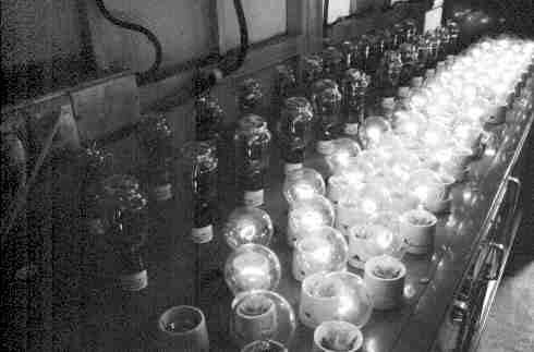
Light bulbs as current limiting devices, in the AVVT tube factory.
(Closed somewhere in 2001 - Read more about it)
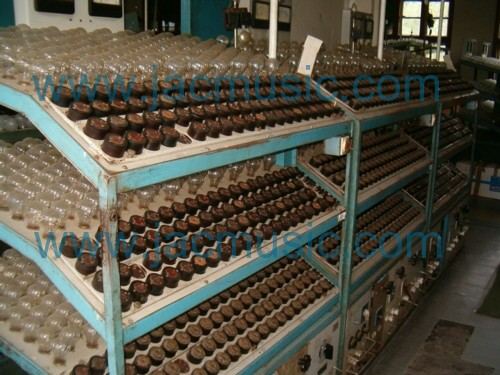
(EI factory Closed in 2014 - Read more about it)
At first I thought, a lamp is just a resistor, which resistance changes with the glow temperature,but the electrical model shows more details than just that. Even so, only with temperature coefficient of the tungsten wire, the observations cannot be explained!
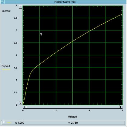
Picture 1. 10V/50Watt Car lamp
This is the plot of current against voltage, of a 10 Volts, 50 Watt halogen lamp from a car head light. Note, the funny nick in the curve.
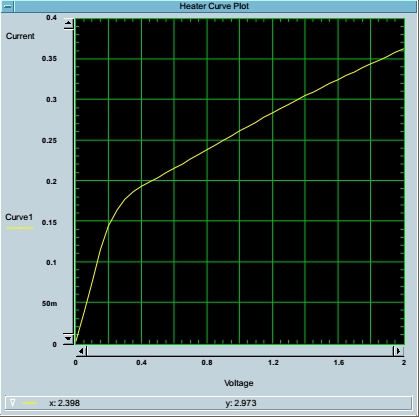
Picture 2. Kalotron Diode2AS15A
This is a plot of the heater of a 2 Volt Kalotron vacuum tube. I took this tube, because I did not want to study car lamps here, and also the car light bulbs are gas filled, and this may have additional effects that we don't want to know about. So the Kalotron tube is better. This is a diode only, and it has an uncoated tungsten heater wire. So it's a bright emitter, it burns yellow at 2 Volts. As you see, here comes the same nick again. In the next picture, we'll try to find the mathematical model for this, and not present the conclusions before hand.
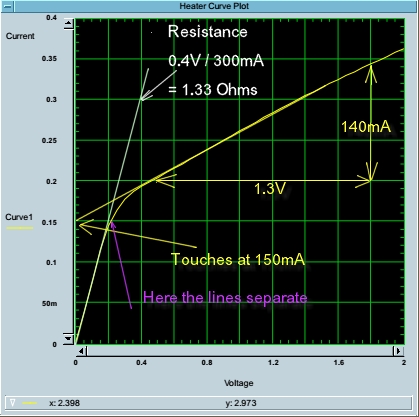
Picture 3. Extract values from the curves
This here is the same plot, but now with some lines drawn inside. You can see here, the heater has two behaviors.
- If cold, it appears a plain resistor, and the expected unlinear effect due to warming up does NOT appear. The resistance is1,33 Ohms.
- The second line, it touches the vertical axis at 150mA, and for the rest is perfectly straight. It changes 140mA over 1.3 Volt. This equals9.28 Ohms. The electrical model of the second line is very simple: I = 0,15 + U / 9,28
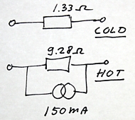
This can be put into an electrical model:
So now, we have the electrical model. Of course what is not interesting is the cold part, as the electron tube is not an electron tube there. It's just a piece of wire in vacuum, and you can only use this value to specify the in-rush current.
The range from 0.2 Volt until 0.4 Volt is something 'in between' where the heater shows both behaviors.
The interesting part is the warm behavior. This begins above 0.5 Volt, and it is a straight line.
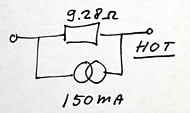
I = 0,15 + U / 9,28
Electrical model of tube heater wire
So this is what we have been looking for. This may look so simple, but it is NOT easy to understand what this is going to do in a circuit. Please note, in the schematic I used the current source symbol, but what I mean to say is a constant current user, I call it a currents sink.
What can you see from this model? Just lets pass current through it, and observe what happens.
- Anything below 150mA would go all into the current sink, and not through the resistor, and there will be zero volt across it. This is an unlogical state,because it's the area below 150mA, and you can see in picture Nr. 3, this is the area where the 'hot' model is not working yet. Meaning you cannot use this model to pass anything below 150mA through it.
- You can also not use the model at 151 mA, as the curve is a mixture here of both models
- Above 200mA this model becomes valid, and you can calculate the heater current at any heater voltage, or vice versa. Just try so and you will see it works at a random point above 200mA
The current sink 'wakes up' above 150mA.
Can we make a conclusion?
It is hard to say what we 'must' conclude from this, but I think we need to pay attention in an appropriate way that a tube heater has a strong 'constant current user' effect, and sure not ignore this. With the 2AS15A here,the constant current use at 0.45 Volt is 150mA versus actually 200mA drawn. So it's almost a constant current user in that operating point!Whereas at a normal operation voltage of 1.8 Volt, we still have approximately 50% of the heater current in this constant current user mode, and the other part in the resistive mode, through the 9.28 Ohms resistor.
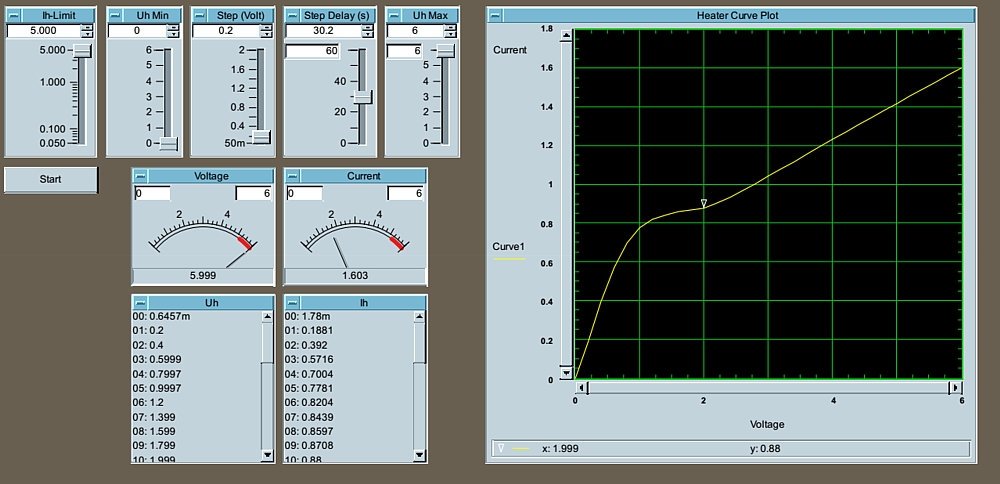
Picture4. Emission Labs 300B-Mesh
Does this apply to this strange Kalotron tube only?
No it doesn't! I used the Kalotron only, because it is by nature a variable heater voltage tube, so there is no discussion about the 'right' heater voltage. The effect applies for other tubes as well.
In the above picture, you see the heater of the EML 300B-Mesh. The electrical model of this tube is even more complicated, as there is a small notch at 2 Volts. I thought this had to do with thermal time constant, from stepping the power supply, but even at those small steps of 0,2 Volt here, and wait 30 seconds before every measurement, this effect would stay. The explanation may be found in the cathode coating layer, so the heater consists of two materials, the metal wire, and the layer on it. I expect this to cause the notch, but I can't explain it.
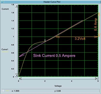
Picture5. Emission Labs 300B-Mesh.
This shows the EML 300B mesh has a 'sink current' of 500mA. This particular tube draws 1.4 Ampere, but this is without anode dissipation. When the anode becomes hot, heater current will reduce somewhat.
The hot, resistive part (Orange numbers) is calculated as:
3.2V / 0.6A = 0.53 Ohms.
This makes the complete formula: I = 0.5 + U / 5.3
You can try it out, it works in every part of the figure, above 2 Volts.
An observation I made, is the following:
- You can mark on the left where the 'sink current' begins. Here, it is 500mA.
- On the 500mA line, you go horizontally to the right, until you touch the real heater plot (The yellow line). This point is where the first part of the heater plot ends to be straight. So now the curves part begins. This confirms, the constant current user 'wakes up' at exactly 500mA.
- You will see this also confirmed in picture #3. For better detail, choose Picture 4, this is the same picture.
Conclusions:
- This modeling is just by trying it out. I have no proof what it causes, but if somebody knows more, I will be glad to place it here.
- Unlike what I used to believe, a tube heater is NOT something with a continuously increasing resistance. Rather it has four different areas.
Area1 - In picture #5 from 0...0.6 Volts, I see fixed resistance of 1 Ohms. This first part of each curve is a straight line, but WHY? I don't know and to me it seems unlogical. Somebody told me, he expects the heater will get rid of all heat in vacuum. It just radiates away, completely. Well, that may sound like the explanation, but if that is so, the heater would never heat up...
Area2 - In picture #5 from 1,8 ... 2.5Volts, the tube does what we all expected. So we see a 'curve'. Resistance goes up as the wire gets warm. So yes this makes sense.
Area3 -In picture #5 from 1.8...2.2 Volts. It curves also, but in the opposite direction. So at higher heat dissipation,dynamic resistance goes DOWN. This is really weird.
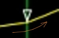
Note this in the above pictures, it is where I have set the marker.
Area4 - In picture #5 from 2.5 ... 6Volts. A fully straight line.
3) A tube heater in it's normal working point behaves not like a resistor. It behaves highly unusual. It must be seen as a constant current user, with a resistor in parallel. This can become very relevant when the tube heater is not supplied by a fixed voltage. Please be well aware of the constant current user character,which is the reason you cannot blindly connect it to an electronic current source. Compare this in the next picture. We all know you can connect two hard voltage sources in series, but not in parallel. Current sources behave similar, butt hey are NOT identical. You can parallel current sources, but please be aware you cannot serialize DIFFERENT value current sources. Where does the difference go to? Unexpected voltages would occur. If you do something illegal with voltage sources, unexpected current will flow. If you do something illegal with current sources, unexpected voltage will occur.
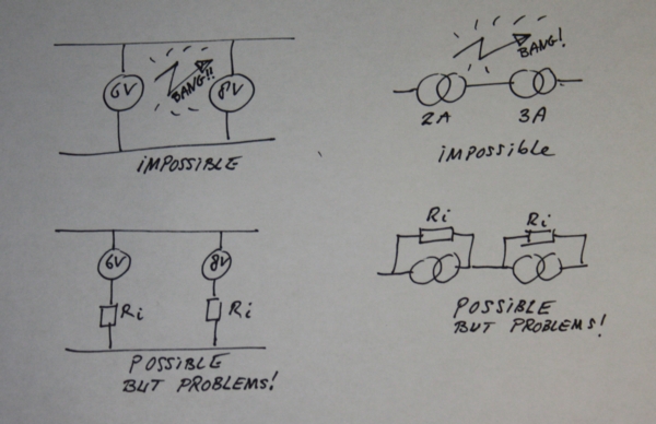
Making calculations with current sources is something you should try and practice until you get the understanding for it. Before you do, be aware that in tube datasheets, often there is no tolerance on the heater current specified.
A word about tolerance. There is a widespread misunderstanding, if tolerance is unspecified, you can take 10%. This is wrong, and I don't know where this 10% is coming from. (If you do, let can me know).If some number is unspecified,you need to make sure you are safe without knowing it. Even so, it can be a terrible mistake choosing 10%, and you destroy the product. Or similarly you do a perfect job, you choose 0%,but....the product has 10%. (and that 10% can be up or down).
When you serialize tube heaters of different manufacturers, or different date codes even, problems begin. Even worse is, serialize a tube heater with an electronic current source, and use the supply current from the tube datasheet. Reason being simple every tube will always have SOME tolerance, but you don't know the value. Now.... what will you do.... Take 0% suddenly? Why not 10% now? So a tube with a datasheet value of 1.2 Ampere, just imagine it has 1.4 Ampere. Just because it has that, and you read only 1.2 Ampere in the datasheet, and you pump 1.2 Ampere through it. You think you do a great job,but in fact you are under heating the tube, and the heater will damage within500 hours. Or overheat is by a mistake in the other direction.
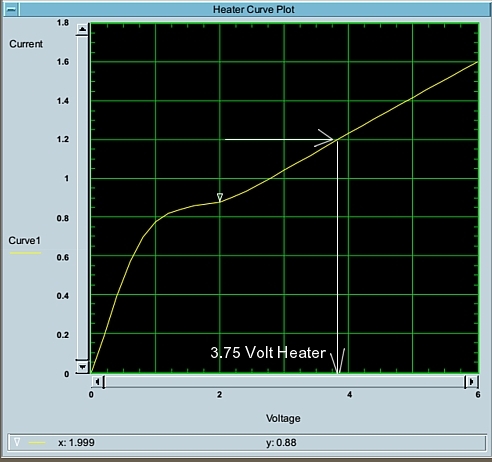
Picture6. Emission Labs 300B-Mesh.
Take for instance this300B-Mesh from picture 6, and see the conflict of two different set points for the current. Suppose you would blindly pump 1.2 Ampere into the tube electronically, because Western Electric said so. Now, the tube gets heated with 3,75 Volt only, winch is 25% too low.
So you see, you are 25% too low, whereas this tube draws normally 1.4 Ampere instead of 1.2 Ampere. Which is 'only' 16% higher.
Conclusion: When you drive this tube with a current source which is 16% lower than the datasheets says, the Heater voltage will be....25% lower! So the mismatch between the currents makes things worse, and not better. Typically this is what happens when you serialize devices that are NOT Intended for it.
If you still want to use a current source to supply a300B tube heater, make sure it can ADJUST it's value. So you adjust it NOT fort he current of the datasheet, but adjust it for 5 VOLTS, by measuring the voltage across the real tube, and by changing the set point of the current. Be aware the heater voltage must be +/- 0%, and heater damage begins at +/-5%. So+/-5% is NOT a limit below which it doesn't matter. It is rather a limit above which damage occurs. This is a limit to stay away from.
Main conclusion:
Respect a tube heater for what it is. They are either manufactured to be voltage driven, or current driven. So ECC88 is voltage driven, and PCC88 is the same tube, but current driven. That is achieved by a different construction,and a different specification. If you want to do something REALLY GOOD for the tubes, do not voltage drive a current specified tube,and vice versa. In some very few, very exceptional cases,you can do it either way, which you can recognize because then it will say so in the datasheet. Generally, and this is for 99,99% of the tubes,a tube is either voltage driven, or current driven. I hope this article helps you understand this better, and why it is never a good idea to do it opposite as in the datasheet, and expect something 'better' from this. Since tube heaters have a lot to do with lifetime and reliability, you can expect problems in that direction, when you do things not as it is written in the datasheet.