Subscribe or unsubscribe our Mailing
List
© COPYRIGHT NOTICE All Rights Reserved

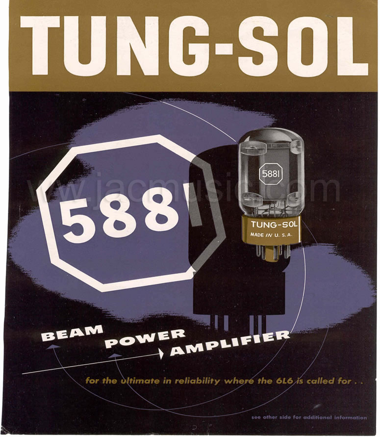
5881,
A new beam power tube
By C.E. Atkins
Commercial Engineer Tung-Sol
Lamps Works, Inc.
As published in Radio &
Television News, September 1950.
POWER output tubes get rough
treatment. Amplifier designers, in an endeavor to obtain maximum output,
frequently operate the tubes at, and sometimes beyond, established ratings.
This has been especially true in the case of the 6L6 and its glass equivalents,
the 6L6G or 6L6GA. As a result, failures are some-times too common, particularly
in continuous duty service. Some of these tubes have stood up remarkably
well, but different production runs of the same tube type often vary considerably
in marginal situations where some special characteristic is being exploited
or where it is necessary to rely upon the stability of some certain parameter
under extreme conditions.
Power tube failures are usually due
to gas. The presence of gas in the tube results in ion bombardment of the
cathode so that its emission is ultimately destroyed. Gas difficulties
are cumulative inasmuch as a small gas content may result in grid current,
lowering the operating bias and thus increasing the plate current. The
greater plate current produces more gas ionization and hence more grid
current, further decreasing the bias and initiating a run-away condition.
Furthermore, the increased plate current results in greater heating of
the tube electrodes which, in turn, may cause the release of additional
quantities of gas.
While gas is frequently the final cause
of cathode destruction, it may not be the initial culprit. All tubes can
be made gassy if heated sufficiently. There are always at least minute
traces of oxygen, nitrogen, carbon dioxide, and other gases in the tube
elements and in the glass or metal envelope. The degree of their removal
during the manufacturing process is a relative sort of thing, depending
upon the temperature and duration of bake-out and bombardment. If a tube
in service approaches this temperature, it is likely to become gassy and,
of course, the temperature of the electrodes and envelope depends upon
the severity of the application. When a power tube is operated at its maximum
rating, various kinds of spurious behavior may push the dissipation beyond
what is considered safe and normal. Parasitic oscillations are by no means
uncommon in power amplifiers, and there is reason to believe that tube
design is a factor in their incidence. Grid emission will, of course, initiate
the same lethal cycle described in the case of residual gas, In power tubes
especially the grid is prone to emit electrons thermionically arid, as
in the case of gas, the resulting grid current changes the grid bias, often
raising the plate current and overloading the tube. Of course, in the case
of both gas current and grid emission current, there is a distortion of
the grid signal which is also undesirable.
Cathode emission failure is not invariably
due to gas ion bombardment. In many applications tubes are employed where
standby operation is a feature of the service. In order that electron emission
be immediately available, the heaters of this tubes are energized, while
the plate and screen voltages are removed or, in many cases, a blocking
voltage is applied to the control grid sufficient to shut off the plate
current. Many tubes lose their cathode emission when operated for protracted
periods under these conditions. This phenomenon has been called "sleeping
sickness." It is roughly analogous to the atrophy of body muscles or organs
after long periods of idleness.
For a long time there has been a growing
demand for a tube with dynamic characteristics like the 6L6 but of a design
that would cope more vigorously with the problems encountered in a heavy-duty
audio output tube. The Tung-Sol design and development engineers,
after considerable experimentation, have evolved a design which embodies
many features which should qualify it as a successful candidate. This is
experimental type DT281 (the RTMA commercial number is 5881). It has some
intriguing features of interest to the reader.
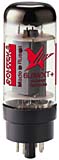
The tube is short and stocky to insure
mechanical ruggedness. With shorter active electrodes alignment is more
readily maintained, This is especially important in a beam power tube where
electrode configuration has the additional function of beam formation in
order to produce the high density electron cloud in the screen-plate space
for the suppression of secondary emission from the plate. The electrodes
are carefully secured to arrow-head shaped top and bottom micas, on three
edges of which mica side-snubbers have been pinned, By this means the walls
of the envelope enlist in the support of the "mount" (tube jargon for the
electrode assembly). The electrode leads are brought in through a glass
disc-called a button stem instead of the flat vertical press stem employed
with the 6L6G-GA. This radial arrangement with liberal spacing of the leads
through the stem is insurance against breakdown due to electrolysis in
the glass. Also, it is believed to render the tube less susceptible to
certain kinds of parasitic oscillation.
Extra precautions have been taken to
deal with gas. The tube is, of course, carefully baked, adroitly bombarded,
and thoroughly pumped. The massive plate of carbonized nickel is three
times thicker than commonly used. It is painted with zirconium, which aids
in the adsorption of gas during the life of the tube. Stray gas molecules
coming in contact with the zirconium surface, adhere to the metal and are
prevented from entering the active interelectrode space to interfere with
thermionic operation of the device. To clean up exhaust gases and effect
the continual removal of gas from the tube by chemical means, a pure barium
getter is used. Three getter flags are currently employed.
To deal with grid emission, the grid
electrodes are given special treatment. Thermionic emission, so essential
in a cathode, can be dangerous and damaging when it emanates from other
electrodes in a tube. All metals emit electrons thermionically if they
become hot enough. The free electrons in a metal, which render it conductive
and contribute to many of its metallic properties, are in a state of agitated,
continual movement. They are prevented from jumping out of the metal at
its surface by the action of electric forces at this boundary, which tend
to keep the electrons inside the metal. When heat is imparted to the metal
the electrons become increasingly agitated and may develop sufficient momentum
to jump out of the metal in spite of the surface force tending to keep
them inside. This surface force varies with the different metals, being
low for some and high for others. The lower this force the more suitable
the metal may be for use as a cathode to supply electrons thermionically.
When thin layers of different metals are built up in a special laminated
fashion, the surface forces are still further reduced. In the oxide coated
cathodes now extensively used, some such arrangement is provided which
results in relatively efficient electron emission.
Now the control grid is necessarily
close to the cathode. There is never more than a few thousandths inch between
the cathode surface and the grid wires. Accordingly, it is very easy for
cathode material to condense on the grid wires after evaporation from the
cathode. This may occur in the process of tube manufacture or later during
the life of the tube. The sensitive cathode materials may form films on
the grid wires, providing a fairly efficient source of thermionic electrons.
The grid's proximity to the cathode makes it vulnerable in another respect.
There is considerable heat energy in the cathodes of power tubes and this
naturally has an elevating effect upon the grid temperature. Because of
the temperature the grid can assume, plus the likelihood of its surface
being contaminated by cathode material, it is easy to see why grid emission
is a common occurrence. Of course, the emitted current is minute,
being on the order of a few microamperes instead of the milliamperes or
even amperes emitted from the cathode. However, where there is a lot of
resistance in the grid circuit this is all that is necessary to cause a
lot of trouble.
In the 5881, grid emission has been
dealt a severe blow by the use of gold plated wire on this electrode. Cathode
materials do not effectively contaminate gold-plated grid wires and hence
the possibility of grid emission is greatly reduced when the grid surface
is gold. Furthermore, gold itself is not an efficient electron emitter.
Naturally the standard power tube practice of copper side-rods,
carrying heat away from the grid to a "black body" radiating member in
the ends is used here.
The screen grid, being farther from
the cathode, is not as vulnerable as the Number One grid, although it is
by no means immune to the same diseases. Since it takes current, it develops
heat on its own account, unlike the control grid which is heated by other
electrodes in the tube. Small amounts of emission current can often be
tolerated, but there is always a limit. In the 5881 the screen grid is
painted with a special carbon suspension which is quite porous and, of
course, very black. Its color, as any physics student knows, increases
the radiation of heat away from it so that it can run cooler. The porosity
of the carbon coating is useful when the tube is used under circumstances
where secondary emission from this electrode may be harmful. It
is believed the secondary electrons are trapped in the porous labyrinth.
Also, the porosity is necessary to facilitate de-gassing this electrode
during the manufacturing process.
Cathode failure (or "sleeping sickness")
during standby periods is combated by using a cathode sleeve of high purity,
grade A, electrolytic nickel. It is generally more difficult to process
cathodes with this type of sleeve, but exhaustive tests indicate a much
greater stability than with the nickel alloy cathode sleeves commonly
used in electron tubes,
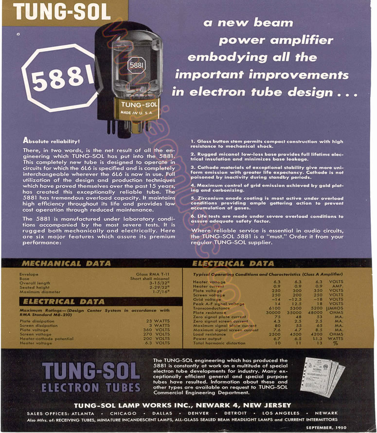
The 5881 carries ratings similar to
the 6L6, except that the allowable screen dissipation is 3.0 watts instead
of 2,5 watts while the maximum plate dissipation is 23 watts instead of
19 watts for the 6L6. The tube has a low loss micanol base. Preliminary
tests give results, which augur well for the future of the type.

Subscribe or unsubscribe
our Mailing
List
© COPYRIGHT NOTICE
All Rights Reserved