Notes about building a Low Noise pre amplifier, using the EML 20B-V4
Description
There is always great disappointment, when a self build pre amplifier appears to be microphonic, and produces an audible amount of noise and hum. This article will some pay attention to low noise, low hum design, and how to use the EML20B-V4 is used in such environment.
When an amplifier is noisy, this can be white noise, hum or microphonics. Noise is just anything unwanted, but do need to divide it into a few categories.
- White Noise this is caused by the electron cloud inside the tube. Some tubes have this more than others, the larger the gain, the more noise. And also the smaller the heater power, the more noise. The sound of this noise is not disturbing, and can't be heard as soon as music plays.
- Sputter Noise this is caused by gas, which is more a talk item, then a real issue with tubes. Gassy tubes are so rare, I was able to save just a hand full of them over 25 years, just to be able to test such.
- Disturbances Tap noise. Tapping on the tubes causes breakage of the heater, loss of emission, grid to heater short, and many more issues. Protection comes from the excessive heat of tubes like KT88, and users prevent to burn their fingers on it. The EML 20B However, doesn't get very hot, and the desire to tap on such tube is shear unresistable for some. Of course you will hear then: Bang... Bang... caused by the grid resonating inside the anode. To be precise, not the grid as such resonates, but the wire pieces of the grid. Same as guitar snares. However during normal use, the mechanical path to the grid is via outside glass, has almost no coupling just via the room. Just don't tap on the tubes, and there will be no tap noise.
Chassis noise. This is caused by tube microphonics via the tube base. It can be heard if switches are operated, or in case of bad quality mains transformer, even mains hum can mechanically be transferred into the tube. Susceptibility for this is low with 20B-V4, because the tube itself is heavy. The tube weight becomes an advantage if the socket itself is mounted in soft rubber pieces. (We sell such). Like this it becomes harder to vibrate the heavy tube via the chassis.
Acoustic coupling. This can not be judged by tapping, because the mechanism inside the tube is another. This kind of noise can be judges if the music is extremely very loud and then suddenly muted totally. Some distinct echo effect can heard. This is part of the tube sound. In snare instruments such effects take place with a much larger effect. Even so, at a piano, the higher octave is not damped at all. These snares, evn if unplayed, produce continuously higher harmonics of the other snares. So you can presse the middle C tone of the piano, and when your finger is off the key, the damper comes back on the snare, and the tone is gone. But not on the highest octave of the piano! These snares give some continuous (soft, brilliant) ringing. Also some damping technique for guitar playing where you damp the snares every time, makes the guitar sound a bit dull, with less "room" sound. So acoustic coupling with tubes is normal, and not something to fight against. And no, you can not judge that by tapping. If you think this, you misunderstood. These are the even harmonics of the music notes. With tubes, this is a natural effect, and should not be seen as something bad. You won't hear that with transistors, same as digital piano sound generators miss the overtone ringing of the higher (undamped) octave, as an acoustic piano has. In short, do not fight tube microphonics as such. Only do something against it if there is a problem. .
If noise becomes too much. In such a case, the blame is quickly found to be the tubes, when some tubes have more of an issue than others, and exchange tubes can solve the problem. However, the root cause may be another, and there is often a relation with (bad) circuit design. Some circuits are more noisy than others, and some tubes are more noisy than others as well.
Leslie 122RV, a perfect NO-NOISE amplifier.
 I was deeply impressed, when I investigated the amplifier of my Leslie 122RV cabinet, connected to my Hammond B3 organ. The 122RV is a huge active loudspeaker box, with a rotating horn speaker, a stationary speaker, and a high efficiency Alnico 15'' bass speaker in a rotating drum. The bass response goes below 33 Hz, which is the lowest tone of the Hammond Organ pedal, and seems to have no, or little sound pressure loss. So I tried how well the 122RV responds to a 50Hz signal, and the sound pressure coming from that little 6550 amplifier began to vibrate the glass of the room windows violently. It is amazing how high the efficiency of that bass cabinet is, and yet it is fully 'dead' at no input signal. As you can understand I wanted to understand how they did that. I found some surprising design details. The RV122 cabinet has no mains plug of it's own. Instead of that, they connect the cabinet with a multi purpose cable to the organ, which cable holds the 230V AC wires, the ground wire, and the tone input signal. Even so, they add a DC voltage to the tone signal in order two switch the motors. Doing so as if there is no such thing as hum problems on this planet. But hey.... the RV122 Cabinet is dead quiet! Even the length of the cable I use is 10 meters, because it's just how long they normally are. My first surprise was to see, there is no shielding used for the tone signal. It's just a fat mains cable, with seven wires inside, instead of normally three wires.
But there is more. When I looked deeper into the amplifier design, I was expecting so see all kind of special constructions to eliminate the hum problems. The least I expected was DC heating of course. But.... none of that at all. All tubes, including the pre amplifier, are simply AC heated. Then I looked at the DC power supply, too see how extremely well it was stabilized. Again nothing like that at all. Just a tiny little choke of 1 Henry. Today people work with 20 or 50 Henry, and have still residual hum, blaming the tubes and the capacitors. Those old designers of the LESLIE company, did not seem to have such problems.
I do not remember the exact value if the AC ripple, but it was in the range of 35 Volts on the oscilloscope, and at higher output power, the ripple increased terrible. And NO HUM whatsoever, even not from a 15" high efficiency bass speaker, in a cabinet of half a cubic meter.
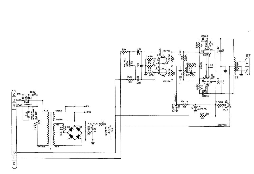
Here is the full version of the schematic, including the motor controls, but it's easier to understand when you look at the edited version, with only the amplifier part. Needless to say, this amplifier has no audible microphonics too. Even with all of those motor parts inside. Look on youtube.
I can't dig too deep in the design of this amplifier, but it is just proof such design are possible, with simple constructions, carbon resistors, and small capacitors, a tiny choke only, and an unshielded tone input with a 10 meters long signal input cable. Just of course there is no foolishness inside. Everything you find there, is done with brains, and profound knowledge.
I noted this: All transformers are fully shielded, and the mains transformer is a very high quality type, definitely oversized. So please keep this in mind as an old hint from the past, just for in case you think mains transformers are unimportant and may as well be cheap. I looked into this masterpiece of a no-hum amplifier, and I can tell you, there was no money saving with the mains transformer and output transformer.
I admire such products, and my personal lesson from this was, the key to low noise tube amplifier, is a clever design, and oversized and high quality transformers.
And not: cheap transformers, thoughtless wiring, knock it together by trial and error, and when it appears to work, oversize the capacitors, and lots of shielding, to get the hum out, and blame the tubes for the rest of it.
With the above experience in mind, I tried to create a concept for low noise amplifier with the 20B-V4 tube.
This article will try to give some good examples of low noise circuits, using the EML20B-V4 tube.
This is not a complete cook book, for how to do this, but these are some good ideas published here.
Important points to take care of (unsorted)
The wooden board test set up.
Build the amplifier first on a wooden board only. Like this, you don't have the advantage of a shielded housing, and any error will become now much more nasty, but for that reason easier to locate. For instance a cheap mains transformer, will give problematic field radiation, when it is on a wooden board, and probably not so much when it is on the outside of a metal chassis. Yet the challenge is, not to have this pollution in the first place. Not, just let it exist, and try to make the construction insensitive against it. You will never be 100% successful with that. On a wooden board, you will notice the hum depends a lot on the angle, where you place it, if and how wires are laid around it, and in what distance. Yet a really good transformer will give you much less of such problems and you can easily find a good position for it. The same applies for non-star grounding. When you just ground things just anywhere on the metal chassis, there is a risk for ground loops. With a wooden board, you are forced to make a good star grounding, or you will never get anywhere near to good result. When you are done, simply use the SAME lay out inside a metal chassis, and you did a perfect job.
A wooden board method is ideal to find your own mistakes.
PART I. Use 20B-V4 as a pre amplifier.
The Leslie Cabinet used indirectly heated tubes, but with directly h heated tubes, I would say, a DC heater supply is standard. Important is, to build the heater electronics like a local module. Please be wise, and so do. Also when you hand wire it on the bread board. So put this electronics somewhere separately, and in the end what comes out, us only a red and a black wire, with 5Volts floating.
In case of hum source finding, feed the tube heater with a battery, made of 4x rechargeable 1.2V Eneloop battery cells. That will immediately tell you if the heater power supply is good, or not.
Hint: When testing the functioning of a new build 5V power supply, do not use the 20B-V4 as a test load. Better use an old 6Volt 5Watt or 10Watt car lamp for that, they are a lot cheaper to replace.
Use a high quality mains transformer. It should come not as a surprise, but the expensive ones are a lot better. Cheap transformers use smaller cores, also made of inferior material. This does not mean they do not work, but the problem is for AUDIO and for LOW SIGNAL applications. Such low cost transformers have the iron magnetized closer to saturation, simply to save money. Also the smaller core saves copper wire length, because 200 windings on a small core have less length than 200 windings on a large core. Even so, it allows the wire to be thinner, when the core is small. Which is another money saver. The disadvantage However, is, it works too close to saturation. By nature such l transformers will have a higher magnetic hum field, if not encapsulated by metal caps, and even such caps will not fully shield it, because magnetic shielding is not done with cheap caps.
Magnetic fields can and will radiate into high impedance wiring or components, and the electric field is high because of the mains voltage on the primary. (Note here there are electric- and magnetic hum fields)
We all know that shielded cables do not pick up hum fields easily. By the same principle, shielded mains transformers do not RADIATE electric hum field. The effect works in both directions. The shielding can be done by metal caps, or better by a copper foil which you see around some professional transformers. However, magnetic stray radiation is very hard to eliminate, once it is created. Whereas electric fields can be at least shielded, magnetic fields cannot be shielded easily. So the clue is, having a transformer which doesn't radiate in the first place, and you will have little to worry about. The magnetic field can propagate easily 30cm through air, and inject hum signals into low signal wiring or directly into electronic parts, also tubes. It is very hard to find out in such a case, where the hum comes from. This is difficult to measure, as signal voltages of this are low, and the frequency is low too.
50 or 60 Hz? 60 Hz transformers, will not work on 50Hz, unless the core is 20% oversized. There is great misunderstanding, this is compensated by the power reserve. It is not! So a transformer, but made for 60Hz, may hum on 50Hz, even when unloaded. There is such a thing a the maximum time, a positive half wave can stay, and then voltage must reverse, or saturation would come. So if the 60Hz transformer is designed on the edge for this, it will hum at 50Hz. This may become hidden issue when you live on the USA, and build something for export. The mains transformer must have 20% more iron that way. To verify if a 60Hz transformer can be used on 50Hz, disconnect all secondary wiring, and only connect it to a primary voltage with a variac. If it doesn't hum at 138V mains voltage, it can be used at 50Hz region. Test this, because it's very high on the list of errors.
The tubes are humming. Are they really? I don't think they do, because there is no 50Hz generator inside them. So where did that 50Hz go in, when it obviously comes out? That is the question. Sometimes people think 'the cable is humming'. Same thing here. What goes in, is what comes out. Often, the mains transformer is radiating a magnetic AC field, into the devices that you think are humming by themself. So if you intend to save money at the wrong place... Save it at the mains transformer :)
In it's simplest form, an (air coupled) transformer consists of two pieces of wire with some proximity to each other. To prevent constructing such unintended transformers, it is always a good idea to twist wires that supply energy to whatever part. (If there is only one wire it becomes harder, but often there are two wires). This twisting needs just a little bit. So don't drill the wires like crazy, this doesn't help more. You achieve a few things by twisting. First, this will not radiate almost not field anymore, because the one wire radiates a field opposite to the other. Second, you can make no funny couplings anymore. As an example, take the AC output winding of a transformer. These carry a 'pulsed' signal from (or to...) the rectifier diodes. This is a nasty wave shape, and often a high energy signal too. It may pass at some point perhaps a signal wire. If course you would never hook that signal wire THROUGH the twisted AC wires. However, when the AC wires are not twisted, you may effectively hook, or loop that signal wire indeed with the AC wires without knowing, and generate an inductive coupling inside the wire spaghetti inside the amplifier. This is really one of the most common wiring mistakes in DIY amplifiers.
Put the volume control not at the input. I have no idea whatsoever, why people LOVE to do that, because I don't see any purpose or advantage for this strange place of the volume control. The price you pay for putting the volume control at the input, is severe loss of signal to noise ratio, and very much increased microphonics. A pre amplifier carries low signal, at it's highest just 1.5 Volts. For this reason, it is no problem to have the input signal enter the pre amp without attenuation. It is still low signal and no tube distortion will occur by just this. However, now we place the volume control at the output. The effect of this is very positive, when we listen to music at low volume, because now there is a lot of attenuation by the volume control. This attenuation will also attenuate tube microphonics, tube noise, and transformer hum problems if you have any. Of course when you set the volume control to maximum, tube microphonics etc will not be attenuated anymore, but at maximum volume the MUSIC is not attenuated. So all things fall into place, and the signal to noise ratio stays good under any condition. The amplifier simply works as expected.
So the volume control at the input ( of a pre amplifier) is strange. When you see any advantage for that, you can let me know, and I will add it here. For myself I see only problems with this. The only restriction is perhaps, when you really have not a low enough output impedance even to drive a 1000 Ohms potentiometer, it will not work. Only seriously, that would not be a good pre amplifier anyway if it cannot drive a 1000 Ohms load.
Volume control at the output is only possible when the output impedance of the output stage is a multiple factor lower at the volume control potentiometer itself. Moreover, we achieve an interesting advantage, that at very low volume, the output impedance at the potentiometer becomes very low. This is very useful to suppress any noise coming from the input (yes!) of the power amplifier, or suppress hum picked up by bad cabling. Particularly such a problem could appear at no, or very low signal, but it is just here where the volume control output impedance becomes that low. (Close to zero). Read one of the next points for how to achieve a low output impedance from a transformer + tube combination.
The output impedance of a transformer output is not what the manufacturer tells you. This would only be true, when you also use the input impedance as he said. Like when you have a 3k to 8Ohms transformer. So yes it is 8Ohms, but only when you connect it to a 3k source. When you connect it to a 6k source, you get 16 Ohms from the same transformer. So output impedance can only be calculated, and it equals the impedance of the signal source, divided by the square root of the windings ratio. In the 'ultra low noise' 20B-V4 amplifier, we use an 18:1 ratio by connecting the LL1689 in Lundahl recommended wiring scheme 'Alt R'. The 20B-V4 has appr 4k5 Ohms output impedance. We make excellent use of the high gain (20x) of the 20B-V4 here, because we can attenuate the signal now by a factor 18. So the output impedance of the LL1689 will be a stunning low value of 4500/(18*18) = 13.8 Ohms . To this must be added the DC resistance of the windings, which is also very low, because for 18:1 all secondaries are in parallel. It delivers a value of appr 20 Ohms. Still exceptionally low for a pre amp, and take note we get that here without any feedback.
To add gain to the pre amp, we use a step up tone transformer from Lundahl. LL1570 can give a gain factor of 2x, provided we load it with medium (not too low) impedance. And this is what we use the 20B-V4 for. It provides also an adequate load to the LL1570. So the preamp has a gain of 2x in total.
Another way to get 2x gain and work without input transformers, is to wire the output transformer 9:1 (this is 'Alt Q' wiring). This will work good as well, just not as ultimate as with the tone transformers. in Alt Q, the windings ratio is only 9:1 and so the output impedance will rise, and also DC resistance of all output windings of the LL1689 is not in parallel anymore, so will be higher. 4500/(9*9) = 55.5 Ohms. Add to this now 19 Ohms copper resistance and we have 75 Ohms at the output. This is still considered very low, and by itself no compromise. We do However, 2x the noise level of the output tube, as we are using the output now as gain stage actually. (So gain is now 2.2x vs 1.1x for the 18:1 configuration). This 'doubling of noise level' much seem frightening, but it is a doubling at very low level anyway. It may be an alternative to try the pre amplifier first in 'Low Noise' configuration, and you are probably satisfied anyway. In case you want to achieve a better result (so 3dB improvement) you can still add the LL1570 transformers later, and modify it into the 'ULTRA Low Noise' configuration.
An optional advantage of the 'ULTRA Low Noise' configuration is that the tone transformers also break a possible ground loop if there is any. Moreover this allows a real symmetrical input, which is not only for lovers of XLR cabling. You can achieve such a groundless connection also with RCA connectors, by using a type with isolated ground, like from Yamamoto Soundcraft from Japan. This is only possible with a tone transformer input.
Biasing of this amplifier is made adjustable, so you can design your own power supply, and in case the +250Volts are not quite that value, you can easily adjust the bias to 18mA anyway. You can go a lot higher then +250 Volts. In case you have such high voltage, you cannot adjust the bias anymore, simply take a larger value for the bias potentiometer, and it will work again.
The tube 20B-V4 is a very nice combination of high gain, low output impedance, and low distortion, being able to work from 250 to 600Volt plate voltage. At 250Volts there is a limited voltage swing, but that is the only limitation, and we do not need much signal here.
The combination of this tube, with the Yamamoto Teflon socket, and the Yamamoto black wood baseplate, gets even nicer when four of the silicon chassis dampers are used to mount the base plate.
PART II. Use 20B-V4 as a head phone amplifier.
There is some similarity with a pre amp. Hum considerations may perhaps seem not so extreme, as the head phone amp is the last element of the chain. Yet, sensitivity of head phones is very high, so low levels of hum may still becomes audible. We can say requirements are equally high. One difference with a pre amp is, due to the lower impedance load, we cannot place the volume control at the output anymore.
Impedance of driving source for head phones.
There is common understanding, the driver source impedance should be considerably lower than the head phone impedance itself. A good factor is 8x or more. Any factor significantly below 8 may be result in a silkier sound, decide for yourself if you want so, but bass will be more imprecise too. So myself, I do not recommend this. A factor 8 is just fine as a minimum. A higher factor is fine as well, just when it becomes too high, sound may become sterile. For that reason, we adapt the output impedance for high impedance head phones, but using a higher impedance output transformer.
Low Impedance Head Phones: For use with head phone, we use speaker output transformers. LL2735-B is specially designed by Per Lundahl, in cooperation with Emission labs, for use with the EML 20B tube. With this transformer, the output impedance will be 2.5 Ohms, and this is suited for headphones of minimum 8x this value, so beginning at 20 Ohms, up to 100 Ohms.
Higher impedance headphones: These will need somewhat more voltage than low impedance head phones, and also sound better when driven with not such a very low impedance. For those we use LL1664 which is originally a 3k to 8 Ohms transformer, but it will behave different when driven with 20B. We should judge LL1664 here, only by the windings ratio which is 19.2 : 1. This will result in appr 12.5 Ohms, taking transformer copper resistance in account also, making the output suited for headphones of 100 Ohms or higher, up to 500 Ohms.
Schematics:

Low Noise pre amplifier with 20B-V4
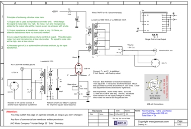
ULTRA Low Noise pre amplifier with 20B-V4
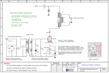
Low Noise Head Phone amplifier with 20B-V4
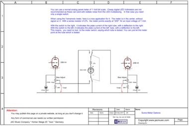
DC Meter Options

Example of how nice such meters can look. (Details here)
Use good Sockets, with chassis dampers
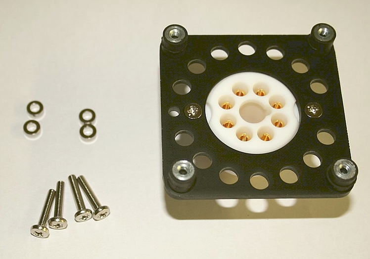 This picture is with a four pin socket, but for use with EML20B-V4 an octal version exists also. This construction is best for low chassis microphonics, using the silicon damper devices (not clearly seen on this picture). Check under Yamamoto sockets for this, at the jacmusic website.