Electron Engine ™
Printed Circuit Boards by Emissionlabs
EE21, EE23, Gold plated Board V6.5. MC Applications
- Overview
 MC Applications (you are here)
- MC Tuning
- All Connection Schemes, Complete Overview
- Unsorted Application Information
Moving Coil
| Input | Board | Gain Low |
Gain High |
Core | Characteristic |
| LL1681 | EE21 | 8x |
16x |
Amorphous Iron | Studio Favorite. What goes in, it what comes out. Only version of this series, with FARADAY Shield, for extremely low hum. |
| LL1931 | EE21 | 8x |
16x |
Amorphous Cobalt | Best Sound of Amorphous, 6N 'Cardas' wire. |
| LL1933 | EE21 | 8x |
16x |
Nickel | Clean sound, Low Distortion, 6N 'Cardas' wire. |
| LL1971 | EE21 | 12x |
24x |
Amorphous Cobalt | Best Sound of Amorphous, 6N 'Cardas' wire. |
| LL1941 | EE21 | 1:16 |
1:32 |
Amorphous Cobalt | Best Sound of Amorphous, 6N 'Cardas' wire. |
| LL1943 | EE21 | 16x |
32x |
Nickel | Clean sound, Low Distortion, 6N 'Cardas' wire. |
A good beginning, to have a good end.
The output signal of an MC is only 0.5mV. Then, if we say residual hum is 1%, this would be audible and nobody would accept it. Yet what does it mean at 1% if 0.5mV? We talk about 5microvolt, and this can not be measured in a normal way any more.
We often hear people say: 'I tried everything, but I can not find the reason for that hum. For this reason, AVOIDING possible errors, is much better, than letting those in the system. Trying to solve it later, will probably not work. Causes of hum are always hidden, and at this is at such a low signal level, trying to measure it is impossible.
This is why a "star grounding" is a lot better, because we can connect the star point to some place of the chassis. Then we know for sure, hum can not enter the signal path from there. However, for the star it can not always be hard connected to the chassis. Again, there is a wire, and new the problems can begin from there. Better is to work with a copper ground plane. Due to the large surface of this, it becomes very hard for a hum voltage, to create an audible voltage over such the surface. This is the principle of the EE20, EE21 and EE23 boards.
Some tips and tricks.
These boards should be placed close to the signal source. When possible, lay the wiring on the metal of the chassis, because electric and magnetic hum fields are lower there. Keep the wiring minimum 10cm away from mains transformers, power supply parts, and cabling to those.
If MC signals are used inside a metal cage, shielded cable is not strictly needed, but it is better. Using a wooden case is also possible, but then shielded cable should be used always. When using XLR wiring, XLR2 and XLR3 should be mildly drilled if these are loose wires.
If in a metal housing, the EE21 board is grounded via the screw holes. PCB screws always tend to get a bit loose over the years. So solder a short ground wire in addition, to one of the 'G' connections, and screw this wire on the chassis, firmly with it's own screw.
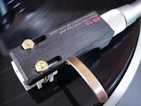
1) Moving Coil, with RCA (Cinch) Connected to turntable.
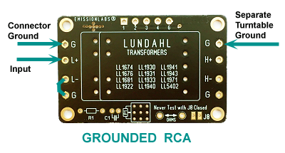 RCA inputs are the most common. This PCB uses a double sided ground plane, shielding also the transformer opening from below.
Using a thick, separate wire for the turntable ground is recommended, in order to prevent AC hum signal to flow through the shield of the RCA cable. Also the connections of this ground wire should be firm, and low impedance.
2) Moving Coil, XLR connected to turntable.
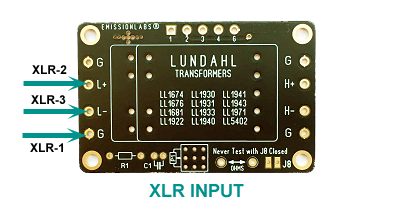
An XLR input is by definition balanced. For MC, this method works only with LL1681 because it has a Faraday shield between primary and secondary.
With XLR, the cable shield (XLR1) forms what is called a "Faraday Cage", in the shape of a pipe, and no electrical stray field can pass to the inside. This is the first protection. Such fields are very strong, and are radiated by mains cables. Next, magnetic hum fields are radiated by mains transformers of all equipment. Such fields can pass the Faraday Cage, like any other magnetic force, and will cause a hum signal in XLR2 and XLR3. These two signals are identical, and are in phase. Since the transformer input will only react to the difference, this will create no input signal across the transformer input.
Turntable chassis. This is normally connected to the XLR-1. If the EE21 board is build into an amplifier, it is best to ground the XLR-1 directly at the connector inputs.
Gain Selection
 Gain can be chosen from two variations. Choose to use solder Jumpers (J1, J2, J3,) or instead connected the external switch board EE22, to 1,2,3,4,G. (See Introduction and gain setting)
Damping of the Cartridge
 This comes all in the end as a final adjustment. First the board has to be set up and make it work. Then, electrical damping of the cartridge can be adjusted. The cartridge is already damped more or less correct by the load of the phono amplifier. Yet not extremely perfect. So fine tuning is a good thing to do, when everything is finished and working. Read more about this in the next part