Electron Engine ™
Printed Circuit Boards by Emissionlabs ®
Tuning the EE20 Board.
First of all, tuning is not necessary for all transformers, and if needed this is written in the data sheet, with recommended value. If not needed, only use the switch, and that is it. For people who fear perhaps the switch will develop a bad contacts over time, just experiment with a few transfer ratios, until you have found the best sounding. Then, at the PCB Bottom add wire pieces across the according switches.
In case is is needed, Lundahl advises a termination network and the value. So in case you just want to proceed by the data sheet, the EE20 board is prepared for this. Yet already here, it can be interesting to switch on and off the recommended network, to hear if there is a difference. For this subject moving coil and other applications require a different approach.
With moving coil, the intention is to apply the correct amount of damping to the needle. This is done mechanically by the manufacturer to some small degree. The main part is done electrically by a termination resistor, at the secondary transformer side. This terminations works at all frequencies. The right amount of damping will give optimized mechanical contact between groove and needle, and best sound resulting from this. So the needle has a tendency not to follow the groove exactly. Damping will prevent this, and improve the sound quality. However, too much damping will make particularly fast needle movements more difficult and there will be a loss of high frequency. Another issue is, the damping for the needle changes heavily when the step up ratio is changed. In fact it changes with the square of this. So when the step up ratio is tripled, the damping will be 9x higher. So the same damping resistor will have another effect, at a change of the transfer ratio. As you see, all of this can nor be advised in a standard way. It is simply best to try it out.
This means first, the best step up ratio needs to be found, and then the right damping at THIS step up ratio. This is tedious to do, when the transformer is hand wired, and people avoid it, though it is important. The solution for this is the EE20 board, both the step up ratio, and the damping resistor are adjustable.
For tone transformers, the situation is another. We do not want to damp the signal over the whole frequency range. Instead of that we no frequency roll off at the high or low end of the audible range, no phase error introduced by the transformer, and no distortion. All tone transformers however have something called self resonance. This means at high enough frequency, the output signal increases by itself. When this happens, distortion and phase will occur as well. It is relatively easy to do something against this. All we need is an extra resistive load, which comes in at the self resonance frequency. This resistor is coupled via a small capacitor, so it will become only effective at the resonance frequency. This works simple and good. When this resonance is damped, it will be gone. So the result is an RC network in parallel with the output. We can change the resistor, to make the network become effective at the desired frequency.
If the data sheet recommends values for this, they are well choosen by Lundahl already. Yet fine tuning can be done as well, to get the upmost out of the transformer. The network can be switched on and off quickly, to hear the effect.
What will tuning do?
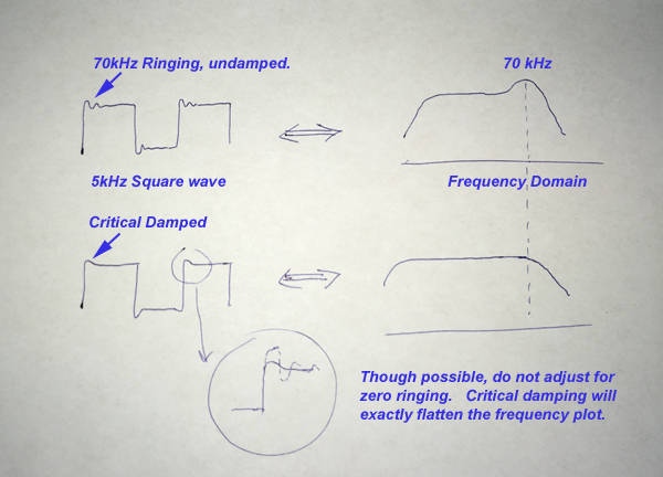
Tuning will give a better linearity and a wider frequency range. It also improves the square wave response at a few kHz significantly. As a rule of thumb, if a system will transfer a square wave of a certain frequency, with so called critical overshoot, the system is be able to do a 10x higher sine wave frequency, at a loss of maximum 3dB.
Self resonance
Having a self resonance point, is something which belongs to every transformer. By good construction, this frequency can be pushed out into a higher range, but at some point it will occur. Doing this right, is the cooking recipe of the transformer builder, and each has his own methods. Franky, do not trust a data sheet which does not give this number.
Self resonance means in a practical situation, the output signal will increase by itself when coming closer to this frequency. When this happens, however a large phase error gets introduced, at relatively small the amplitude error already. Even so, the resonance is not just a little bit, it can be 50% of the signal. As long as a sine wave is within the specified frequency range for the product, self resonance will not take place. This is why some transformer manufacturers do not mention this information, simplifying the subject. Yet all transformers have it, and it's a number you may want to know. Reasons are explained below.
If we apply a square wave within the audible range, like 5kHz, this signal contains higher harmonics, some of which may be in the range of the self resonance frequency, and this causes the infamous ringing in the audible range. This means at every edge of the square wave, for a very short moment, the transformer resonates. Which means adding of new frequencies, which were not present in the original signal before. This means, instead of the expected edge, we see an overshoot which by itself consists of 2...3 periods of the self resonance frequency (with some 10% or more, of the amplitude of the square wave itself). I find it difficult to say, if this is a problem or not. Is looks quite 'bad' to see this in an oscilloscope. But is may become difficult to hear. Still when I hear people saying they can hear the sound of cables, or the better sound of gold plated fuses, I think it is 100x more useful first eliminate such obvious errors which can be demonstrated with a simple measurement.
Here is how it is recommended in the LL1544A data sheet.
![]()
The functioning of the tuning network
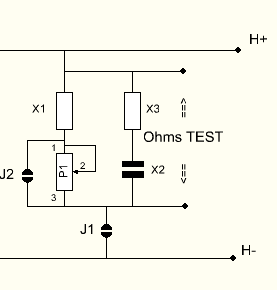 One the EE20 board, we use a network consisting of with two resistors a potentiometer, a capacitor, two switches and a test point. This gives a lot of flexibility. We will recommend a few options, but feel free to tweak it as you like.
- R1+R3 is a variable resistive load for all frequencies. R2 + C1 add an extra load starting at a choosen frequency.
- Jumper J1 switches the network on and off, this is needed for quick sound tests. Also J1 must be opened to measure the damping resistor represented by the total network. Otherwise this would damage the transformer, and besides we would also measure the DC resistance of everything H- is connected to.
- Resistor R1 is just a minimum value, it prevents a shorted output, in case the variable resistor would be set at zero. Furthermore, R1 can be replaced by a capacitor, to have an adjustable RC time constant via R3. In such a case, the fixed damping can be achieved by shorting C1, and use R2 as fixed damping resistor.
- Jumper J2 is for the audiofiles, and the final thing to use. If all adjustments are final, there may be a concern, such a cheap PCB potentiometer can cause problems later on. It can be replaced by a fixed resistor, which comes at the position of R1. For this, open J1 first and measure the total resistance via the test points. Then take a fixed resistor of this value, put it at the position of R1, and close Jumpers J1 and J2.
This little sections is all we need.
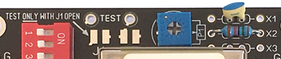
PCB potentiometers have different pin connections and dimensions. With this board lay out, all normal types will fit in.
For adjustment there are a few ways.
Example here for LL1544a.
- Use the data sheet. These are average values and in any case good. For LL1544A for instance, the data sheet specifies 6k7 and 470pF for the RC network. Insert those values at R2 and C1. Activate the network by closing J1. Like this LL1544A is wired by the data sheet. The next part is about more precise adjustment, using an oscilloscope.
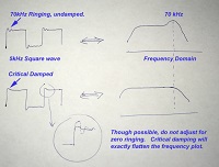
- Adjustment with an oscilloscope. I will replace the hand sketch by an oscilloscope pictures later.
 For an adjustable option, insert the capacitor of 470pF at the position of R1 at the board. The variable resistor will replace the 6k7 resistor and it's value should be 10k. J2 is open and J1 is closed. Now the network can be fine tuned for what is called critical overshoot, this is a quick and very reliable methode to get the best adjustment.
What no Cartridge Manufacturer can say in advance.
Not a part of the transformer specifications however, is the reaction of the MC cartridge to amount of damping. The RIAA amplifier, to which the EE21 board is connected, is assumed to have 47k impedance, which they usually have indeed. This is not the issue. However this impedance is transformed to the MC side by the square root of the transformer gain. Which transformer gain is NEVER specified by the MC cartridge manufacturer. So perhaps one chooses a gain of 10x or 20x. A gain of 10x will have only 25% of the damping compared to a gain of 20x. So depending on what MC transformer is taken, there will be quite a change of damping of the cartridge, which is only by coincidence the right one.
In short we can say, at too much damping the sound becomes dull, and at to little damping the needles looses good contact with the groove. How much damping is ideal, depends also on the weight of the head shell and stiffness of the tone arm. All of this can never be specified by the manufacturer, and they will avoid the subject, by just say what is the "minimum" load and that is all. So this is why we recommend variable damping, and switch it on and off, to hear for yourself if there is the difference.