Since 1993 Copyright Notice
SERVICE INFORMATION FOR
VAIC REFERENCE 32B, 52B, 62B MONOBLOCK
Introduction
In case you want to do service on this amplifier, voltages inside are exceptional high. You should only do this yourself when you are a qualified High Voltage Technician, and trained on this particular product too. All service work as described here is only how I would do it myself.
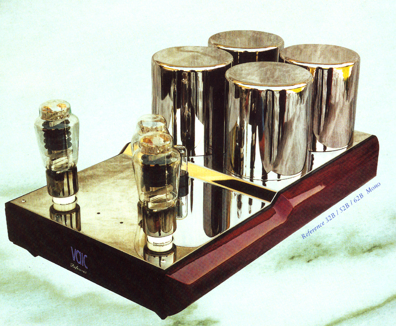
I scanned this from the official Catalog, that is with the amplifiers.
This new price of those was 21.000 Euro including taxes, including AV8B driver tubes, but not including power tubes.
These are the reference models.. and hey... that's what they are. If you look inside, it makes your heart beat faster. All triode amplifiers, no feedback. Directly heated driver tube AV8B, and 6SN7 input tube. Gold plated connectors. Even the bias switch at the back for the bias control is gold plated. It has an RCA and XLR connectors input, you can hand-adjust the bias yourself, with a precision build-in digital reading. After adjustment, the digital meters can be switched off, if you don't like the red- letters of it, in the dark. So you'll see the tube glow only. The amps has tube rectification, 6SN7 preamp tube, and a beautiful directly heated driver tube AV8B, and two 1605 or 520B output tubes, Parallel Single Ended for each mono block.
Note, that this amp allows to do a tube replacement without having to send the amplifier to a company. The user can check the status of End Tubes tubes and re-adjust them periodically as needed. It may not seem important now, but it will be after some years of use, and it's a MAJOR advantage of this amplifier over the lower class VAIC models.
This is the BEST and largest VAIC amplifier EVER MADE. There has never been a larger or a better one.


It consists of TWO mono blocks

IMPORTANT NOTICE ABOUT THE METERS.
These meters are expensive industrial meters, but they have one disadvantage, maximum input voltage is 30 Volts and above that they damage. This 30V can happen when there is a spike on the mains, or when you do a setting above 30V by mistake, when you knock on the power tubes by mistake, etc. Read below, under "service" how to prevent this.
Some small service may be needed after all those years. Actually this is amazingly little ever since 1998.
- Add 50mA radio fuse in meter circuit.
- Set the voltage to the power tubes right. You cannot say what tubes were in there before, or what settings somebody made
- Replace the 12V light bulbs under the VAIC logo. Like all light bulbs, these last several thousand hours. These are normal light bulbs same as used in a car. If the lamp is broken, the amplifier has run at least 4000 hrs.
- Tighten all screws from the inside. This includes the screws of the transformer pots.
- Check and/or improve the ground wire to the chassis.
- If there is crackling noise in the amplifier, replace the anode resistors of the AV8B tubes when they are from the "RS" brand. Or don't even wait for it, just replace them. They are very difficult to replace on the same position. The screws are just behind a transformer. You could mount the replacements on another place, and just leave the old ones in.
- AV8B driver tubes are often weak.
- Power tubes are often at the end of life.
- The high voltage selector needs cleaning (read below here) .
- Input impedance is 55k. This is wrong, and useless. It gives only too much noise, and when your pre-amplifier can only drive 55k, throw it away and buy real one. To cure this situation, add a 10k Resistor over the RCA input.
- Fake XLR input. This is the only critic I have. Really, this was not needed. If you want to fix this error, add the EE20 PCB to the amplifier at the inside. This can isolate the RCA input and XLR input at the same time. Search in the EE20 page for "XLR input + balanced RCA input simultaneously"
- In addition, the EE20 board has programmable gain or attenuation, and should be set for Gain = 0.5x. So attenuation of a factor 2. Like this the sensitivity of the amplifier is reduced. Of the EE20 board is used, there is not need to add a 10k resistor to the RCA input. Instead of that, this impedance correction is now done with the EE20 board. At EE20, close Jumpers J1 and J1, and add 10k at position X1. Set the Piano Switch to 1, 3, 7, 9, 11 . Or, for Gain =0,75 Set the Piano switch to 1, 3, 5, 7, 8, 11. Or, even combine EE20 with EE22, and the gain becomes selectable from the outside, with a small switch. The switch can double the gain. So if set for 0.5x it switches to 1x
 Inside the meters is an over voltage protection, but this is something like a Zener diode. So functioning is very limited, this Zener diode will burn out also, and then the meters are damaged. The meters are still for sale at RS Electronics, but they cost 250 Euro each. (Blue ones exists too). To protect the meters, simply add a small radio fuse into the V+ wire to the meters. That is the center wire of the meter switch. These meters have only a V+ wire and a ground wire, and take their own operation power from the voltage itself. The value of this fuse is 50mA. The internal protection can blow such a fuse, and then the meters itself will not damage. Please take this serious. This is the only known design error in this amplifier, for the rest it is perfect. A replacement of such a meter is a TERRIBLE project, it takes a full day. You need to remove the power supply board completely, and the transformers partially, and even the old meter needs to be hacked out as it's clamped in with a steel clip. The potential risk of wiring errors when desoldering the whole power supply board is large. So don't save on a 50 cents radio fuse.
 On the power supply board are two selectors that allow to change the power supply voltage to the Power tubes. (So not to the rest of the amplifier). The voltage selection is done by choosing transformer taps. So there is AC signal on those selectors, coming directly from the transformer. This is meaningful, as 520B-V2 tubes needed higher voltage then 300B tubes, and 1605 needs the highest voltage. The selectors have each three settings. One selector is for "coarse" and the other is for "fine". So one gives big steps, the other small steps. Just measure the high voltage on the anode of the power tubes, and you will see what they do. These selectors are made of a small clamp with a screw, and some solder work is done on the PCB. It looks good on first sight, but when you take it apart, and desolder everything with desoldering litz, you probably see the solder was a bit loose underneath, and there is the risk of a loose contact, or a short. Moreover, the solder is much too thick, and solder by itself is never intended to take mechanical force. If so, over the years, it will flow, and the contact can and will become loose. The amplifiers I serviced, needed not just resolder it quickly, and tighten the screw, but it was needed to remove the solder completely, clean it well, and resolder it nice, but thin. So use as little solder as possible.
High Voltage Switch Setting:
- 300B: Low or Medium
- 520B-V2 Medium or High
- 1605 High
Output transformers
These are litz wound, and have two output impedances, 4 and 8 Ohms. In case you are using very sensitive 16 Ohms horns, you can use this Parallel Single Ended amplifier with just one tube per channel, thus giving half the output power, which is enough on that case, AND this automatically produces doubles the output impedance, because we have parallel output tubes but use only one in that case. So we have 4 and 8 Ohms outputs at full power, and the option to have 16 Ohms at half the output power.
Pre-heating electronics
This is a nice feature of most of the VAICs, and these have it also. The tube heaters are warmed up at first, and pre-heated at 20% anode current. During this time the sound is shut off. Then, after the warm up, the anode current is ramped up gradually which takes 2 seconds, and the amplifier starts to work without any click noise, and no stress for the tubes. This is done with the NE555 timer, the most classic timer IC ever, so in the unlikely case it needs a repair, this can be bought easily. That being said, this part and the digital meter, are the only integrated circuits you find in this amplifiers. All other electronics is analog. Even the lamp behind this panel is a light bulb, no LED. From experience with other users, we know this light bulb is the only serviceable part inside. This is a normal light bulb as with cars, so can be replaced easily.
 |
 |
 |
Power Off |
Pre-heat. Dark blue |
Run. Bright blue |
Short specifications:
- All tube amplifier, with 5U4G tube rectification
- Output Power: 50 watts per channel with EML 520B Tubes
- Output Power: 60 watts per channel with EML 1605 Tubes
- Frequency Response: +/- 0 dB 7 Hz-35 kHz; +/- 2 dB 5 Hz-100 kHz
- Two Outputs: 4 or 8 ohms
- Input impedance: 55 kilohms
- Signal-to-Noise Ratio: 98 dB
- Input Connectors: RCA, XLR
- Weight 55kgs, for one mono block.
- Dimensions (cm): 37.5 x 60 x 27
Some of the highlights, I may even forget some here:
- Rhodium plated deck + transformer cases.
- Gold plated hardware at the back RCA and (FAKE) XLR input
- Litz Wound output transformers.
- Mains transformer, chokes, output transformers, all separately encapsulated, and potted.
- High temperature wiring. Transformer wiring partially with glass fiber sleeves. Solid red wood sides. Polished, Piano lacquered, very thick layer. Can be internally configured for a VERY large choice of output tubes.
- Driver tube is AV8B. This tube has appr 5000 hours life time. Old stock is very hard to find. We have some blue glass versions for sale still. With some internal modification, AV8B can be changed to Emission Labs 12B.
- Tube exchange, can be done by technical end user, amplifier can stay closed.
- If opened, the mains voltage can be adjusted for 110V, 115V, 120V, 220V, 230V or 240V.
- Output impedance 4 or 8 Ohms at full power. The 8 Ohms output can be used at 16 Ohms at half power.
- Different bias levels of output tubes is possible. You can save tube life if you need not full output power. Also you can choose for specific sound at relatively low bias, which you may prefer when using very high efficiency speaker. You have all options open here.
- Digital meter control of bias level. Bias setting with very precise, wire wound, 10-turns device. Can be done by the end user. Use the setting holes in the amplifier deck, and a screw driver. Read bias level from the digital meters. A reading of "20" means 100% bias. A reading of "10" means 50% bias, etc.
- Many of the very expensive AUDYN Foil caps are used.
- Pre-heating electronics with very high functionality. Absolutely ideal system, which gives you the best tube life.
- Uses all classic circuitry, no tricks or strange things. Any good technician can service this amplifier now, and 25 years later.
- We have the factory schematics. We charge 80 Euro for it, there is no charge if you buy replacement tubes from us.
- Universal output connectors, for forks, wire, or banana plugs