Repair Report of Neuberger RPM370/1
THIS REPORT is not so much about how the RMP370/1 works in detail, but more about restoring one.
It is set for 230V, but all voltages are possible. Virtually EVERYTHING was checked, repaired, or calibrated, etc. What is not done, and not really necessary is a case repaint. But if the new owner wants to do a perfect job here, this may be nice idea.
What is NOT with it, is the test card set, but I do have a CD with a perfect quality pdf scan of each card. These cards print very good on a normal printer and dimensions are exactly correct. Hole size of the cards is appr 5mm and uncritical, so any standard punch tool can be used.
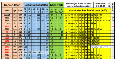
Also with it, is a universal test card, in color, and a 60 pages manual, with the settings of appr 2000 of the most used tubes with it, and this can be expanded with new tubes. Just take a similar tube, and you have already the electrical connections. So all you need to adjust then, is the voltages at which the new tube is set, and what is the expected reading. Suppose, you want to test the Russian 6N6P, just look for a near equivalent, which is: ECC99, or E182CC, and all you need to do is, adapt the test voltages. Similar, you can test an 845 or 211 when you use the 300B connection scheme, etc. Also at 500V, the 845 can be tested, and the expected readings can be taken from the tube curves. You can just plug in the 845 socket in the blue field of the below card, with banana cables.
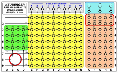
I was given this card for my personal use only, and I keep it only with this tester.
Use it as a 6x output lab power supply.
Highly underestimated, is the option to use this tester as a lab power supply. You can connect simply everything with banana plugs! You can set it upright on the bench, and it won't even take much space like that.
- Any heater voltage needed, with meter reading.
- TWO separate adjustable negative grid voltages up to -100V, with meter reading.
- TWO separate adjustable positive grid voltages, up to 500V, with meter reading.
- One high current (Anode) voltage with current and voltage metering.
PART2 Electrical functioning of RPM370/1
Introduction
In this category of Neuberger Testers, we have the RPM370, RPM370/1 and RMPRPM375. The predecessor was the Neuberger 352, which is a nice tester actually too, but the 352 is in the "vintage" testers category. In this category of vintage testers some beautiful products can be found, which are an example of engineering quality, and 352 is sure of one those. Some vintage testers usually can test only the tubes of that period, some others were made universal, and can be upgraded easily, or otherwise with socket adapters. The Neuberger RMP370 is not one of those! The RMP370 can actually test most tubes ever made, it just misses some of the really modern sockets like 10pin (decal). Though we have to say, particularly this category of "very modern" sockets never made it, and for the industry, such were a standardization "mistake". The later Neuberger RPM375 focusses sharply on those newer socket types. RPM375 is full of sockets you probably won't need, and it misses many of the normal sockets, like UX4. Particularly the fact that the RPM370 has all the right sockets, makes it such a wanted tester. Moreover, the mechanical construction of the RPM 370 is nicer, and sure much more comfortable with respect to the settings of the voltages. That is because of the red numbers inside a window, which changes. Whereas with RPM375 you need to derive that from some printed texts, and a color combination, and this is just a very nasty saving. At least optically better are the newer looking meters of the RPM375, but these are made of plastic, and all older plastics one day or another will develop problems, such as cracking and discoloring. Inside the 352 (mentioned above) is for instance very complicated, modular switch, which is the heart if the machine, and these may (or may not) suffer crack problems. The same applies for the System I /II switch, which is located inside the test card. These are under mechanical force inside, because of a quite a strong spring inside. These all will crack some day. I have to say, these cracks can be repaired absolutely nice, and invisible, when you fully remove the switch and when you clean and prepare the surfaces, and use professional glue. This is typically -of course- NOT how it's done. So one day, the switch will pop out, and somebody takes some cheap glue, and "fix" it. Some time later, this will break again, but now it gets harder to clean the surface from that silly glue. Just mentioning this here, to explain why old plastics do indeed create problems. And in the RPM370, I found no other problems as that switch. Another reason why I prefer it vs RPM375.
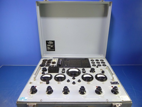
Both testers below here, are my own, but the RPM375 was sold. This report here, is about restoring the RMP370. I have sometimes repaired a RMP370 for people when they are prepared to bring it, and pick it up themselves. From this, I can say issues are most of the time the same. Though the RMP370 is large, lots of space inside, etc., still you can not reach everything easily.
Solder Joints can be a problem. After 70 years, it is always a question if the solder is still good. I once had a RMP375 for repair, and each and every solder joint was bad, or at least suspected, and I could not reach all of them. Also, just re-melt the solder iron is fully useless. The old solder may flow at the surface, but not inside, where the bad connection is. You really need to REMOVE all old solder, as it is contaminated, and will never re-solder reliable any more. The joints looked optically not bad but when I pull on a wire, I could sometimes pull them out of the solder joint easily. And then you see, the surface if the wire, inside the solder joint, was dark colored by a layer chemical stuff. This will only re-solder at great heat, with fresh solder, and lots of flux. Even scratching that layer off, is not easy. Well the good part is, only 1 out of 15 testers is like this, the other 14 are fine. So beware very much, not to buy one like that! Unfortunately you can not see that from Ebay pictures, you only find out when you pull on the fat kind of wires. These can have bad joints. The fragile, thin wires are mostly still soldered good. Whereas the one have restored here for myself, the solder joints were all fine. I have to repeat this really clearly, if you find our your 370 or 375 has solder joint problems, this will get worse over time, and some 5...10% of the solder joints you can not reach. Myself, I would never want to own a tester with such potential problems.
Loose meter glasses is a standard problem. You don't really see that very well, and it doesn't seem to matter much because even a loose glass will stay mechanically at it's place. But it DOES matter, because magnetic dirt will creep in over time, and the meter becomes sticky. Also normal dust will come in, and cause fungus (black dust) stains on the scale, which can not be removed fully if you wait 25 years too long with it. As a second problem, this fungus will damage the lettering. So re-glue the glass nicely, when loose is very important. That means taking out the glass, not just drip some cheap glue on it, while leaving the meter in.
The main meter meter (the big one in the center) can be damaged by overload, and this meter is hard to repair. Not because it is not nice build, but because you can hardly take it out, there is all kind of wire and other parts attached to the meter itself. Also inside, the meter is build a bit difficult. So the needle is a bit off balance, which you may see, when you put the tester upright, and the meter reading becomes another. Or, you may see it by the meter offset screw, it allows to set the needle very far to the right, but almost not to the left. Or vice vera. If that is the case, the needle was bend over a little bit to one side. The good indication for such problems, is to set the meter for a 50% full scale reading, and then check what you can do with the centering set screw. This should be able to change the needle reading equally to the left or to the right.
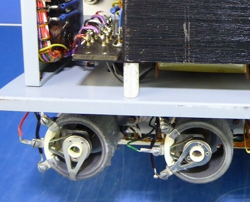
The Rheostats are always a MAJOR problem with faulty testers, so beware you don't buy one with defects, which you think to fix quickly. Probably you will not be able to fix those at all. I will not tell you my secret tricks here, but in case you have one with a broken wire, I probably can repair it for you. The Rheostats of this tester, described here, were all good, they just needed cleaning and lubrication. All in all, this tester appeared hardly used, which becomes visible when you take off the finger of the Rheostats, and you can see the wear of the center contact. A lot of wear means also the resistor wire is scraped off to some extend, and one day will develop an open contact.
For the repairs here, there is no particular order, items are just listed here as they came up.
There are two versions, RPM370 and RPM370/1, of which the newer version, RMP370/1 has foil capacitors for the high voltage, and more precise (cemented) Rheostats. Since many people don't know the difference anyway, prices for RPM370 and RPM370/1 are the same, but RMP370/1 is the preferred one, if you have the choice.
I may keep it or sell it, I don't know yet. It is indeed a tester which can do an amazing 500V, easily reprogramable for any other tube, and also you can put an ampere meter in every tube electrode. This is simply done by remove the appropriate current link, and put an ampere meter inside. Also, there is a field of banana plug holes to connect a voltmeter to any electrode. These are one of the very few testers capable of this. Even so, with the banana plug holes, you can connect a hand made adapter box quickly, which connects to tubes like the 845, or provisionally do so by clip crocodile connectors on the other end of a banana cable. This is really a great feature of this tester.
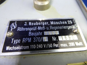
Neuberger RPM370/1
Neuberger RPM375
Number of RMP370 made.
 I will try to find out how many are ever made.
The first model was called RMP370, starting in 1950. After that came RMP370/1 in 1953.
It seems to me, they numbered the testers throughout the years, so appr 2000 were ever made. Given, many people seem to own one, probably most of them have survived.
This is what I found in the internet:
1950 RMP370. Series nr 102
1953
Series nr 382
1954 Series nr 897
1955 Series nr 1229
1959 Series nr 1659 RMP370/1
1959 Series nr 1690 (My own)
1962 Series nr 2052 RMP370/1
Ebay Prices seen
July 2019 1600 Euro / Series nr 1659
July 2019 1999 Euro / Series nr can not be seen. Some parts missing
The scales of the RMP370 vs RPM375
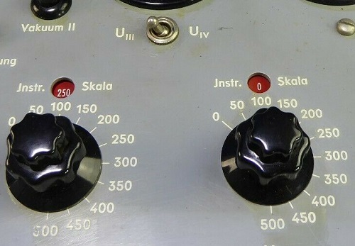
The scales are definitely done better with the RMP370. Let me pay some attention to this, because it's done so nice! When you select a voltage, automatically the scale of the meter is switched, which I have seen with no tester. This seems so normal when you see it here, but it is a luxury. It works like this, look at the knobs. Each of those (five) knobs have an outside knob and an inside knob. With the outside know, you select the maximum voltage you can apply, in steps of 50V. So the outside number is just a safetly limitation. The meter scale is something else. The meter scale is 250V, for a setting of 250V or 200V. With the inside knob, you can go from 0...200 on 200V or from 0...250 on 250V. Yet at 300V you can go from 0...300V at a meter scale of 500V. This works so nice and so natural, you almost don's notice, but it requires a lot of hardware, and you can hardly make a mistake.
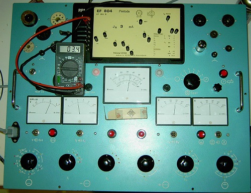
Look at the below RPM375. You can see they saved on the hardware.
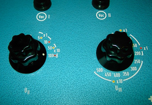
With RMP375, it is solved electrically the same way, but you need to perform a multiplication yourself, in order to find meter scale. I used both RMP370 and RPM375, and I find RPM375 simply confusing. That is when I test tubes, I have my concentration with the tube, and not with multiplying numbers for a 3...4 meters at the same time. You have five meters, and you use normally two or three to set the tube, and a fourth to read it.
The paint work
RPM375 is the clear winner here. The deck is painted beautiful with blue-green hammer paint, and the paint is good quality too. The RMP370 is painted cheaper, but for that, the numbers are engraved, vs printed with RPM375. So one way or another, you can always repair a bad print with the RMP370, but not with RPM375.
The paint itself of the RMP370 however is too soft, scratches easily, and gets dirty. So with a RMP370 you can not be overly critical with paint appearance. Repainting it is possible, but very nasty work. You can lift up the meters easily 1cm, so you can spray underneath, also remove many of the knobs, and most of the switches partially. Some other things you can not remove, and you need to cover them with tape and paint around it. Nasty work, but I assume people did so before. When you care good at re-filling the engravement, I suppose the result will be very nice.
At first switch on.
Dead. No function. Now that is perfect, because the seller probably gave up here, and I know he is extremely busy, and only interested in quick business. After some 20 minutes, I found a loose solder connection, which interrupted the mains voltage.
After I fixed that, the tester worked. I ramped up the high voltage slowly, so to save the capacitors. I stayed at 100V at first. All voltages were terrible unstable. I switch off, and exercised all switches, and that solved the problem completely. So indeed it was stored ever since1995, untested, unknown condition, as the seller told me. For rest everything was working, except the voltage for "instrument adjustment" (like needed for the leakage test) which gets only to 95%, but I will find the cause for that. All this tester needs from here is a check up, but I already know, this usually yields a long list of work to do.
The solder connections.
This can be a terrible problem with the RPM375 and RMP370 as well, but the older solder of the RMP370 seems better quality, and any problems as far as I saw, were rather with the RPM375. If you have a tester with several bad (so half loose) solder joints, it means ALL joints are bad, just you can't see that from the outside. The problem with this is, you can't reach all of them to re-solder them.
The issue with bad solder joints is, too much optimism with soldering. So they simply solder in a 1.5mm thick wire into solder lug, by just stick it in, and NOT bend the end around the lug. If the solder material is not so great, these are the first joints that will get loose. Also many of the small wires are not even put INTO the solder lugs, but just soldered ("glued") flat on the sides. This is an absolute "no" in a production environment, when you know just a little bit about soldering. So such a tester should be re soldered where ever you can.
I do not know exactly why this is so, but humidity seems to make solder connections bad. It seems as if oxide creeps inside, along the wires. Such a wire you can sometimes just pull out of it's solder drop, though it looked fine! Even so, you will find it very difficult to re solder it. The oxide is quite stabile. So check any unknown RMP370 or RPM375 for this issue, and believe me, it can extremely nasty to distrust any solder connection whatsoever. Well, luckily with this tester, all of that is perfect.
The Rheostats.
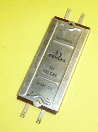
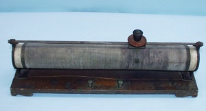 Rheostats are big size variable resistors, on a ceramic core. They are high precision, with or without lacquered windings to keep them in place better. This picture is of an historical Rheostat, of the kind the word was normally used for. Later we probably called them just slide resistors, but Rheostats were precision elements originally, and had little temperature effects.
The ones in the Neuberger RMP370 and RPM375 are quite good items, but 60 years is a long time. Generally, these seem to have a corrosion problem, and it is the #1 question always when buying RMP370 or RPM375: What is the condition of the rheostats? If you forget this, when buying one, you loose.
The Neuberger Rheostats
Why you should always set the knobs to ZERO when storing a RMP370 or RPM375.
The corrosion seems to be caused by the resistor wire itself. In touch with any other metal, it corrodes that metal, while staying uncorroded itself. So the voltaic row of elements seems to play a role here. The slide contact seems bronze, and the wound wire is not bronze, and when different metals touch, a small voltage is created. It is not much, but enough to do damage over a long time. So it is very good practice, to set the knobs always to zero, when you store the tester. I have seen testers, stored for 20 years unused, and at the place where it touched the resistor wire, it was interrupted. However when you set it to zero, it touches the end plate, which is made of nickel plated bronze too. So you have: Bronze-Nickel-bronze. This seems to corrode the nickel layer over time, which by itself is no problem, as the contact remains self cleaning, and you never need zero volts anyway.
Also the position where the resistor wire is connected to the end plate, it seems to corrode the brass connector screws. However that is no problem, so don't feel tempted to scratch away that green stuff. Underneath is an undamaged resistor wire, and whatever you do, it would only damage the wire by mistake.
Another problem is the slide contacts to the rotating finger. These spring bars are made of some bronze alloy, and they tend to corrode at the place where they are bend under a sharp angle. However I was always able to fix such a break nicely by cleaning the ends shiny, and then solder them together with a small piece of copper sheet on it. Solder may look stabile, but it is not! So in a second step, you need to wind a copper wire very tight around the repair spot, and solder that also. I had to do this with one of them.
In case the original parts are too corroded, that is not going to work of course, as the original metal can have even a hole corroded into it, and the slide contact falls off when you try to clean it.
I have a repair method even for a broken resistor wire, but I keep that trick for myself. With this RMP370, this was not needed, the resistor wires were all perfect. It was stored since 1995 as I got it in 2019. It was owned by the German army before, and the last calibration was in 1995.
Luckily it was stored not humid, and (happy....) the knobs were set to zero. Probably by coincidence, but it was so, and I could see the imprints at the "zero" contacts. Which again could be polished off nicely. This is not always so. If stored humid, there can be even a round hole in the zero contact!
Anyway, nothing of that was the case here. Meaning the resistor wire is perfect, no thin places in it. I took off one of the fingers, and from the bronze slider contact, nothing was scraped off yet. So this tester was hardly used. I have oiled and cleaning all Rheostats, and the "feel" is totally another. They turn smooth like new, and you can hear and feel the resistor wire while doing so. Very nice, and this is how they should be. For all mechanical parts, I use "fine machine oil" from Pressol, which is regarded by the Hammond Organ Club Germany, as one of the best oil of new production, which does not react with and residue of old oil. These people really know, so I follow their advise. The resistor wire, I mildly oiled it with silicon oil, though originally it is dry. The dry method is maintenance free, but it has more wear out. So now, it is oiled, you check it for dirt collection every 15 years or so, and re-oil at the occasion, but for that, wear out is only a fraction. Given the Rheostats are so hard to replace, saving their good condition comes first.
The fingers. In case you take off the fingers of the rheostats, be very careful to secure them again with a drop of paint. Same as original. You should tighten them a loose as you can, because they are made of thin ceramic and break otherwise.
The knobs.
Well, a knob is only a knob. However these are very hard to replace. The little knobs at the top, are made of Bakelite, and when you tighten them too hard for no reason, the side will crack off. I have seen often RPM375 with the little knobs missing, so that is why. I checked, and two had a crack already. One was cracked too far, and decided to break it off, and re-glue. A good glue for that is JB weld for metal. That is a dark grey, almost black glue. The other was only cracked a little bit, and I gave it a drop of Acrylate glue. When mounting such re glued knobs, it is better to tighten them very little, and use a mild version of Loctite Screw Securing glue. So the screw won't come off, even though secured just as loose as needed. Such repairs are invisible, and can be regarded permanent.
The Capacitors.
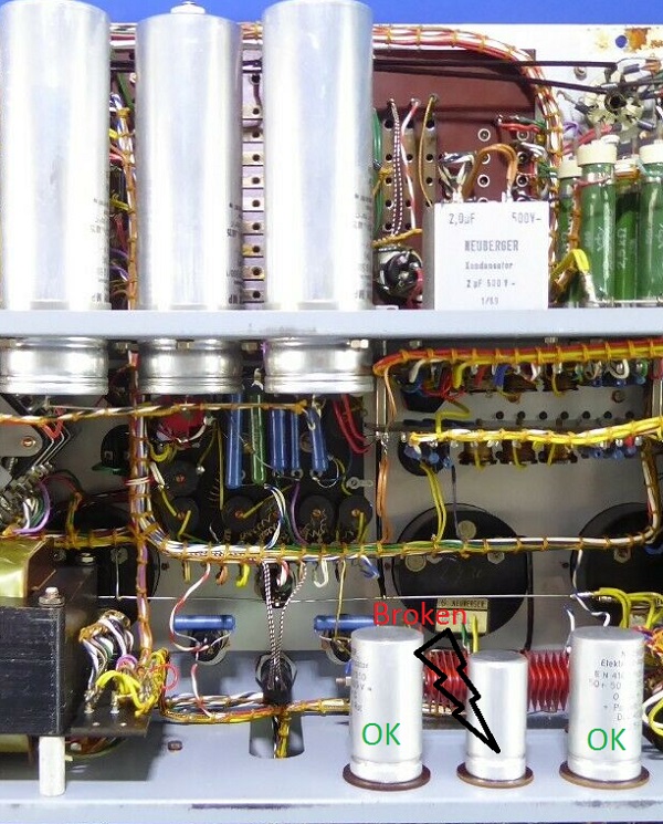
The big ones and the square one beneath it, are foil types with RPM370/1 (not with RPM370), so with RPM370/1 these will stay good for ever. Three smaller ones, below on the picture, are Electrolytic type, and these can be bad after long storage. The large ones, with "OK" on it, are for the negative grid voltages Ug (1 and 2). These were in like new condition. The smaller one on the middle (C6) is for the leakage current measurement, and it is used to generate the DC test voltage for that. This is just a multimeter circuit, and the DC voltage is created from the 110V winding and the (largest) Selen cell diode. At the setting "instrument adjust" you need to set the meter for full scale, same as any normal multimeter. That worked only to maximum 95%. The reason was C6 did not want to charge up fully any more. After replacing C6, that part worked fine also, and the whole tube tester was working good.
The selenium diodes used
Some people talk about Selenium cell, but a "cell" is a light dependent selenium element. The selenium diodes can be seen, behind the three capacitors. A Selen diode to me is a little miracle, because what you get in there, is a fully normal semiconductor, but no semiconductor material like Germanium or Silicon. It works just with metal plates, and oxide layers of selenium and cadmium. Really easy to build. They do have a little bit of a bad reputation, but myself I can not confirm this. The ones I saw, were all good. They work like a normal diode, and reverse leakage is really low. Only forward voltage is several volts, which makes them get hot at high current. Before the coming of Germanium and silicon diodes, miniaturization of those was progressing at GE Labs, but they stopped the program as Germanium became available.
A good thing about selenium diodes, they have a current limiting effect, same as tube diodes. So when an old Selenium diode in some equipment is still good, I sure will leave it inside.
 This here is a final generation similar Selenium rectifier. This is not what is in the tester. I used one like that when I was a kid, to charge batteries, or run a DC motor from AC. I did many, many stupid things with it. I shorted the outputs, and I fried it so hot, you could barely touch it, I soldered the ends 100's of times with my father's old solder iron. It never broke down. I even opened it up, to see what is inside. There were only loose sheets of metal plates, piled on each other. Not interesting to see. After closing it again, it still worked normal ever after. So yes, I believe it when people find broken selenium diodes, but as said, I have seen only good ones.
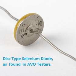 A clear disadvantage is the low reverse forward voltage, so in order to get a high reverse voltage you need to stack many of them. Which again gives a high forward voltage too. In order to deal with that better, Neuberger just used four separate Selenium diodes, which each be itself consists of several more single diodes. So for the negative grid of -5V there is a single diode used, for 10V they use three in series, etc, until a 6cm long stack of them for the -100V range.
Protection
C6 is for generating a -100V working voltage for the multi meter. The voltage must be so high, because many leakage effects appear only at higher voltage. In the rare case, C6 gets defective, the Selenium diode would show it's current limiting effect, but in the end probably gets defective from this, and then the transformer damages. So to prevent this serious damage, there is a fuse (F2) in the transformer winding. And yes, it was needed here. C6 was broken, the fuse was blown out, but the Selenium cell and the transformer were still good.
About Electrolytic capacitors
Some people kick out any Electrolytic type they see, but I rather measure the original caps carefully, and when they are as good as new, they can stay in. I find it is usually a yes-no question. Either they are fully ok, or totally bad. So when the capacitance is above 100%, and the ESR (Equivalent Series Resistance) is just a few Ohms, they are first class condition still. After testing, two of them where like that, but one was a 4V zener diode, said my ESR meter. I took it out, and put it on a Hewlett Packard Electrolytic capacitor tester, and indeed it did not want to charge above 4V without beginning to drawing high current. So my ESR meter was right. Just for interest, I tried to re format it, but anything above 50V caused more than 10mA current. So it was bad indeed, probably caused by the 24 years this tester spend in storage. So now I try to find a replacement part of the same looks and construction, so to keep this tester as nicely vintage as it is n ow. So not solder in some cheap axial capacitor to replace it. I think I found one but it cost me 20 Euro from a special supplier of radio parts.
Meter Accuracy
This is a dream. Reading is fully exact on all ranges: not one meter, not one range is a tiny bit off. Nothing needs to be done here.
Adding sockets
Since the tester is so massive, it can be used to test 211, 845, and 6C33 as well. I intend to do so by adding the missing sockets for this is the lid, and connect this with a plug. Same as with Funke did with the W18.
Case painting
Will be continued
PART2 Electrical functioning of RPM370/1
RMP370, RMP370/1 or RPM375?
At first sight, one might prefer the RPM375, because it looks kind of modern, and of course is not as old, and the big size meters look very tempting. There are a few pro and contra, and I will try to list those here. RMP370 was the first model, with tube rectification, and it was followed up by the RMP370/1. Theoretically, RMP370/1 has the newer better Rheostats, but strangely I have also seen RMP370/1 with the older Rheostats in it. Now, this could have been a repair by somebody, I just don't know. At least, it leaves some doubt in my mind, to go strictly by the designation RMP370 or RMP370/1 but rather go by the Rheostats inside.
The newer Rheostats are cemented type, which has the advantage of a bit more precise fine regulation. The new types are wound with thinner wire, which has to be held in place by the cement. The older types have wire ends which are not as fine, so you have less steps along per rotation angle. I wonder how important that is, because the panel meters are kind of tiny, so you can not see it extremely precise anyway. The newer Rheostats, because of their thinner wire, can get easily damaged, mostly during service, when the whole tester is put on the bench uncareful, and the arms of the Rheostats get a bit crushed. The arms are actually very strong, but wire is thin. So then you end up with the typical broken Rheostats. With the older types, the wire is more rugged. Moreover, the cemented types develop a fat layer of copper oxide often, which is easy to remove unprofessional, but it costs time to take them apart, and polish and probably re-plate the brass contacts with nickel again.
RMP370, what is better than RMP370/1.
- Rheostats do not damage so easily
- It seems to have extra contacts at the switch board, which can be used to attach a connector to, for additional sockets in the lid. Also the lid itself is prepared for this. So actually, this is an EXTREMELY nice feature.
RMP370/1, what is better than RMP370.
- Rheostats are more precise.
- Capacitors for high voltage are foil type.
- The switch board is looking, if used without cards.
RMP370/1, what is better than RPM375.
- The tubes inside give current protection, and a slow start of the whole tester. In case of a severe overload, you only damage the internal rectifiers, which are low cost and easy to find. You can exchange the tubes, via a control opening, without having to open up the whole tester.
- The neon lamp for the leakage test is better visible, which is very important of you want to see very small leakage.
- It has a button for "cathode test"
- It has more sockets. Also older types at that time, but today, these are now the typical used sockets still. So you can test UX4, UX5 tubes, etc,
- It shows directly the meter scale changes. For me a MAJOR advantage. WIth RPM375 you are calculating all of the time, and this is extremely nasty for somebody like me.
- The solder quality. I have seen RPM375 where each and every solder connection was a bit recrystallized, and had to be re-soldered. Problem is only, you can not reach all of them.
RPM375, what is better than RMP370/1.
- It has no tubes inside. There is less voltage drop at high load, like 120mA. This can be (and should be) adjusted during the measurement anyway, so advantage of this is not so extremely large.
- It has meters with a more detailed scale
- The mains chassis plug is not so big.
- The paint looks a lot nicer. The unused plugs are in a "drop" box, which is more convenient.
- The red push buttons of the RPM375 look nice.
Final choice:
RPM375 has no functional upgrade, apart from the newer sockets. Particularly these sockets were though to be the "future" in those days, but when we see what tube people use, and prefer today, this "future" did not come.
At first sight, one might prefer the RPM375, because it looks kind of modern, and of course is not as old, and the big size meters look very tempting. There is no functional upgrade, apart from the newer sockets in the RPM375. Particularly these sockets were of course intended as the "future" in those days, but when we see what tube people use, and prefer today, this "future" came another way. What I find extremely problematic with the RPM375, it misses most of the vintage sockets, which to my opinion would not have been necessary, because there was more than enough space, but actually it was just wasted, by putting the sockets such that there is little space available to add new sockets. Unlike for instance the early AVO testers, which had empty holes for new, future socket types. Not so with the RPM375. So, all the old sockets are missing. You can't test the radio tubes with "side sockets", such as the famous AD1, the beautiful AZ4 rectifier (close to 5U4G) and many more of this series. Also you can't test any steel tubes like the VF14, used in (!) The Neuberger Microphones. No testing of 2A3, 300B, 807, and may more those tubes that are much sought after. For that, getting 10 pin sockets of types that never made it, and nuvistor sockets, is not the right compensation. So for this reason alone, I prefer the RMP370.
Another reason why I prefer the RMP370 is, the power supply for the Anode and Screen voltage is done with tubes. At first you may think, silicon diodes are better, but the good thing of rectifier tubes is, they provide a natural current limiting in case of a short or overload. Silicon diodes can easily supply 5 Amperes for a short moment, and destroy the tube under test, and also easily the transformer of the tester, and other parts of the circuit. So myself I prefer the natural safety of tube rectifiers. So in case you manage to blow up the rectifiers (of type RGN1064) they are not expensive and easy to find, but you can also be happy that is probably the only repair needed. A bit nasty are the selenium rectifiers used inside. They are usually still good, but I have seen defects too. This was not improved in the RPM375! There is the same strange looking stack of Selenium rectifiers in there.
The meters of the RPM375.
Sure, I admit they look nicer, but electrically they are not better. The RPM375 meters are made of plastic, and old meters of the RMP370 are made of Bakelite, which is probably the best long-time stabile material there is. The meter glass is of real glass, so it won't scratch, but it can break of course. The disadvantage of the RMP370 meter glass, we have to say it, the glue is not good, and most of the time the glass is a little bit loose. There is a small protection inside, to prevent a loose glass from falling inside, but this is not much of a protection, and when you try to clean the glass powerfully rubbing it, you may press it inside. Many meters were killed that way. So tap the glass gently with a jeweller's screwdriver tip, and you will hear immediately if it is already loose or not. And when yes, dirt will come in, and you need to fix that immediately. Re-Glue the glass is not difficult, but on the other hand when you have not done so before, don't do it for the first time with your RMP370 meters. When the system is unprotected, you damage the needle perhaps, or magnetic dust comes in. A mistake happens before you know it, and then it gets very expensive to have an expert fix it. Better send the meter "as is" to somebody who can do it, and charges will be moderate. However with the main meter, this is a problem. You can't take it out, there is a large assembly attached to it. You can lift it up however far enough to reach for the screws and lift off the cap. Close to the point where you need force, but them the screws become barely within reach. This very nasty, and not recommended as your first repair of a panel meter! It worked well with this tester when I did it, but when you damage the main instrument, it may be the end of the tester. You will have a hard time replacing or repairing it, and then of course it does really need to be taken completely out of the tester and that is a terrible job.