Since 1993 Copyright Notice
Computer Interface for the L3-3 tube tester
Introduction
why a computer interface for this tester? The reason is, I use this tester actually quite often, because of it's accuracy, because of the many different ways a tube can be tested, and the many parameters which can be extracted. With my own card set, I can test almost any tube I like, and also do some additional things, such as tube burn in, tube Rejunivation, or grid cleaning. However I find it a disadvantage, I need to rotate through all the test results with a knob, and I can not see them simultaneously. Like when I change the grid voltage, I would like to see the plate current and transconductance at the same time. I used to have some work around with external meters, but that is unsatisfactory. So I had the idea to add a connector to the L3-3, tapping all tube data at once. On the L3-3 page you can find a link to the L3-3 project of Marc Michalzik. He is a test and measurement specialist, a real genius. He can (and will) take any defective machine totally apart, and renovate it, with exceptional care for detail or good results. Mark renovated his L3-3 tester, and added a deck of banana connectors at the inside, via which he could do the calibration more precise, and also tap some measurement results directly, instead of using the panel meter. His project sure inspired me, but I was looking for a way to extract more information from the tester, and not adding all those banana connectors.
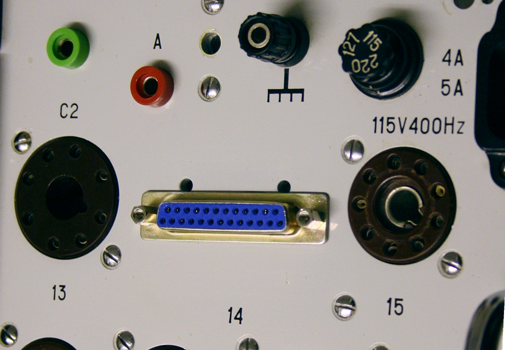
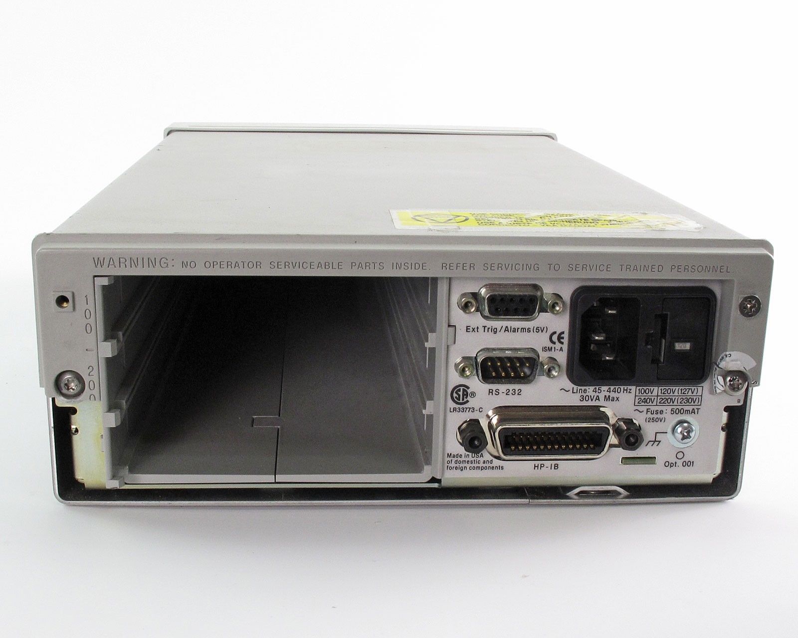
For the connector I choose a 25-Pin D-Type, because they are easy to get, and ready wired cables are low cost. For the place of this connector, I identified two positions. At the front deck, or behind the right lid at the side. When choosing the lid, it is mechanically easier, but I am not so sure if the heat of the power supply tubes will not damage the connector. So I choose for the D-connector at the deck.
The D-connecor comes at the place of the flying lead connector. With my L3-3 this connector was not in good shape, and I never test flying lead tubes anyway. A D-connector and also it's commercial cables, have a maximum voltage specified of 60Volts. This can easily be overcome, by using a 10:1 attenuator for each signal. If the attenuator is high impedance, like 1 Meg, it will not significantly load the circuits, and also the signals leaving the L3-3 via the D-Connector will be short circuit proof. I choose for a 909k - 100k attenuator, resulting in 1Meg load impedance and 100k output impedance. This attenuator I will add 24 times on a small interface PCB. This will go directly to the D-Connector.
At the other side of the D-Connector cable comes a unit, which essentially is nothing but a 24 positions switch and a good quality multi meter. Such a unit I don't need to build myself, these were made by Agilent, and it is called HP34970A. These can use a 24 channel relay card, and have a 6 1/2 digit multi meter build in. You can measure each channel comfortably via the display and a rotation knob, selecting the channel. You can get older versions on Ebay for a reasonable price. Moreover, the HP34970A has the possibility to read all data via an RS232 interface, and then I have all data captured. Once in the computer, I can much more easily process the data. The first thing which needs to be done, is correct for the attenuator factor. Even so, the individual tolerance of the attenuator resistors can be corrected. I just need to verify this once, and store this number in my software. Also, I can now calculate new data from this, which is not directly available, such as Anode dissipation and screen grid dissipation. Finally, I can show all data on one screen. I can make the software give a sign when the measurement becomes stabile, and even export the data to Excel. The Excel file I can read with an Excel program, which then re formats this is any desired way, and this would be the test report. This can be printed in Excel as a pdf.
So far my wish list...
What follows now is a description if the project, as it continues. The first picture is the position of the flying lead connector, which I will remove.

Flying lead connector - Original. This will be removed.

Here it is removed
D-Connector mounted.
 D-Connector from the inside. I used five shielded cables. I don't know yet how many I need for the Gm signals,
I think three, so five as I have should be enough. The thin wires are Teflon cable and is for normal voltages and current. I pulled out the wiring of the flying lead connector all the way from the cable tree, so to make it look more tidy, there is already enough cable in the L3-3
D-Connector from the inside. I used five shielded cables. I don't know yet how many I need for the Gm signals,
I think three, so five as I have should be enough. The thin wires are Teflon cable and is for normal voltages and current. I pulled out the wiring of the flying lead connector all the way from the cable tree, so to make it look more tidy, there is already enough cable in the L3-3
I received this L3-3 tester (#4) with a broken flying lead connector from a seller in Hungary. Now look at this, the hole is almost the same size as a D-Connector.
This interface is intends only to take signals from the tester. Though some possibilities are there for controlling the tester too, I will not begin with that. This would beak my time limits, and also I have no need, since I already have a Sofia, and that can do 700Volts, 250mA. So this is not going to be like the Sofia, or like Amplitrex each working with not very high resolution. Note, this system is going to be self-calibrating in software. The result will be an undisputable 5 digits. Well I hope so. Even when the D-Connector cable and the attenuator compromise a little bit on this, and it is one digit less, it would be fine.

Inside are two bulky diodes. They measure like a few silicon diodes in series. Well state of the art in 1975, but we have better diodes today, mainly smaller size. This we don't need any more.
This cap and the diodes underneath gets removed, to make room for the interface PCB.

These two little diodes replaced the big diodes behind the metal box.

Original Diodes of L3-3 - Just for fun.
It has nothing to do with the PC interface, but I tried to look inside the diodes blocks with the Tektronix 576, and we see several low current diodes are serialized in here. How many, that is hard to say. First, we see this from the forward voltage. The beginning with a silicon diode is around 0.5V, and appr 0.75V (or even more) when you reach the maximum allowed current. That would give: Five diodes. That makes also sense, as we get appr 3.8 Volts at 150mA. Also there is no smallest sign of leakage, at the maximum 1600V as I can get out of the Tek576. Then, we see relatively high series resistance, indicating again many diodes in series. Well, I replaced this by one single modern diode. We are only rectifying 500V AC. Though I can imagine abuse-proof level of these self-made diodes is very high.

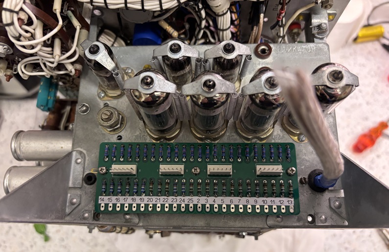
A small change to the cable tree, and soon the bulky diodes can be replaced by small ones. The Original wire can be used for the new diodes. This is the unit with the electron tubes on it, from the right side. All parts on this board were checked, and fine. One foil capacitor was "ok" but not as new. I would normally have left it in. Now I put a new Mundorf cap in there. (The white one)

Finally... The cable three from the D-Connector. It looks such a simple result now. As you can see, the cable tree is 10cm too short. I Good planning would have been better :).
Note, the D-Connector and Cable can only do 50V, but I have a 10:1 attenuator on each line. This makes it possible to measure up to 500V DC from the inside of the L3-3. For in case in some place I may need to measure higher, I can still adapt an individual attenuator. The attenuation factor, will be corrected in software. Also any deviation, due to resistor tolerance can be compensated, by storing the calibration parameters for each attenuator in the software. So I can use simple uncalibrated resistors.
Today the PCB's arrived, I had to order minimum five pcs, but I need only one. If someone is interested to do the same project, let me know.
I have changed the numbering of the PCB, to the same geometry as the D-Connector.
The PCB has 1:10 dividers with 909k/100k. This makes the PCB universal. By default I will use a 909k/100k divider, giving 1Meg input impedance and 100k output impedance. For some very high voltages, perhaps, I want to measure that later, I can still insert other values at one of the positions.
How do I want to measure so many signals?
 First, we have to be realistic about the targets of this interface. Though it may be possible, to control some functions of the tube tester, such as grid voltage, many of the functions which are needed for a fully controlled tube tester, will be difficult or impossible with the L3-3. So I set the target only on measuring voltage and current from the tester. In addition, signals can be taken from it which will (probably) obsolete the Gm calibration.
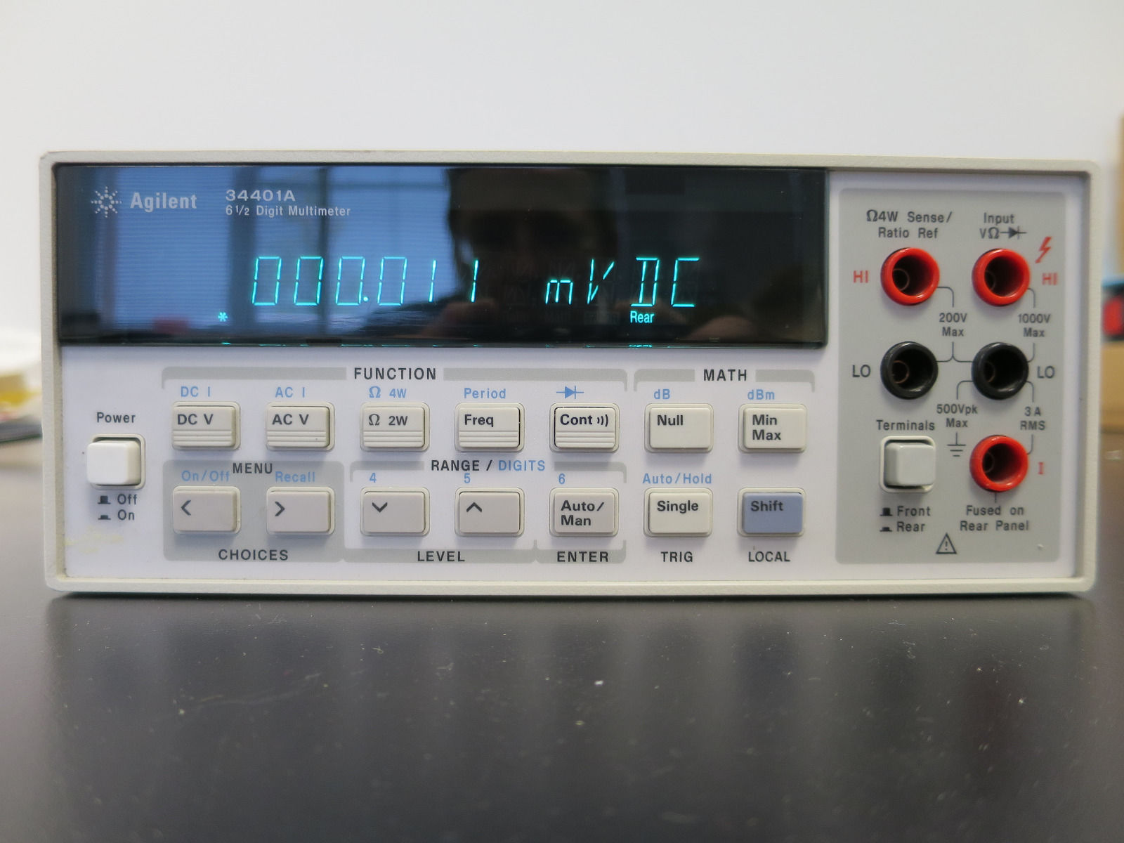
How do I want to measure? That is a good question. It depends on what hardware and software is available for a reasonable price. I think you can buy relatively cheap analog inputs, which connect to a PC, via USB. But then you end up with the voltages in some strange USB program, by the makers of these USB boards, and this is not what I want. Let me bring to your attention, the Agilent 3440A Multi meter. It was a standard for it's time, and there is still nothing wrong with such a multi meter, However it has only two inputs (one at the front and one at the back). Two inputs is not enough, but more about this later. They are still 400 Euro on Ebay, though already so old.
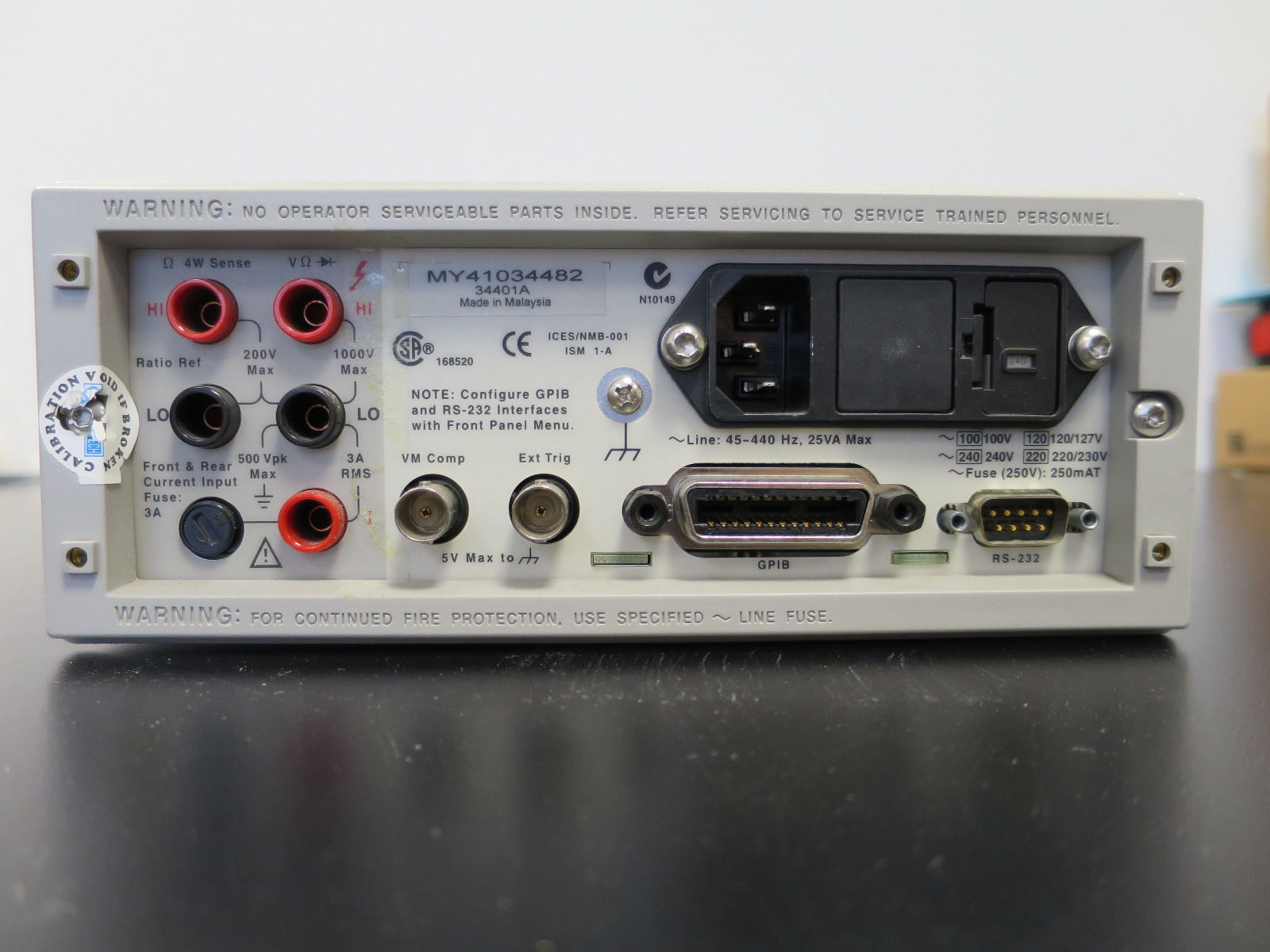 Here is the back of the 34401A. You see once more the same connectors. That is for a permanent set up, so you don't have all the cables hanging out on the front. It is fully programmable via parallel or serial Interface. You can however connect two signals to it, and use the front switch to select. Like measure current and voltage at the same time. Actually very convenient, and not many multi meters have that.
But how to measure 10 signals? I needs a relay board, or 10 meters. Do I want to buy 10 meters, or build a relay board? No.... not necessary. There is something more interesting around, It is called 34970A Data Acquisition unit.
Here is the back of the 34401A. You see once more the same connectors. That is for a permanent set up, so you don't have all the cables hanging out on the front. It is fully programmable via parallel or serial Interface. You can however connect two signals to it, and use the front switch to select. Like measure current and voltage at the same time. Actually very convenient, and not many multi meters have that.
But how to measure 10 signals? I needs a relay board, or 10 meters. Do I want to buy 10 meters, or build a relay board? No.... not necessary. There is something more interesting around, It is called 34970A Data Acquisition unit.
 The Agilent 34970A Data Acquisition unit, is using the electronics of the 34401. It has no connections at the front, but is has two card slots from behind. The most used card is probably the 20 Channel multiplexer. This is simply a 20 channel relay board, which makes it a 20 channel Multi meter, with all 34401A capabilities. You can program each channel by PC, or by hand and story that inside the 34970A. Suppose you decide, channel 1 is for 300Volt DC, and channel 2 is for 10mA AC, you can just store this. After this is done, simply turn the unit on. There is a knob on the bottom right, and you can rotate it from Channel 1...20. So when you turn it in "1" the meter displays a DC Voltage, and when you rotate it to "2" the meter displays 10mA AC current. It has even the option to set the units. So you can make the display show "mA" or "Volts" or any text you like. Well, this is the stand alone operation, but you can also program and read from it via PC. This includes switching the unit on via PC.
On the 20 channel card are 20 wire pairs, of which only two pairs are used in this example. It can even measure temperature with a thermocouple. All you need to do, connect it the thermocouple wire pair to channel 3, and set channel 3 for temperature.
 Here is the 34970A Data Acquisition unit from the back, no cards are inserted. A nice range of cards exists. Even a 20 channel relay card. I only want to measure the tube data digitally and all at once, and be able to print a quality report, which looks the way I want to myself.
The 34970A Data Acquisition Unit, also called DAQ works very nice with Agilent VEE. Though this is a very old program, it is easier to program than Labview, and it will do the same. Besides I already have Agilent VEE. Other users, I would recommend Labview, just the free version.
What signals do I want to measure?
That is not easy to answer now! I do not want to over-engineer the hardware. From designing computer controlled equipment in the 1980's, I remember one principle very well, and that is: Everything that can done in software or in hardware, you should do it in software.
What I want at this moment, is this:
- Make as little changes to the tester as possible.
- The idea is, to set the tester to "transconductance testing" (in German: "S" for Steilheit). This applies both AC and DC to Grid 1. With this setting, using the panel meter, you can only measure transconductance of course. Yet all other functions are active. So Anode Current, Anode Voltage, etc, it is all present inside the tester at some points. It can just not be displayed on the panel meter. HOWEVER, with the computer interface this can all be tested at the same time. So there is no more need to rotate the parameter switch. All parameters, including "S" can be measured simultaneously
- Transconductance calibration is not needed anymore, as we will simply also measure also the oscillator output voltage directly, at Test point TP8. We can just design a formula in software, where the oscillator output voltage goes in as well. In other words: When the oscillator output voltage goes down for instance 10%, normally also the "S" result goes down 10%, but when we divide the result by the oscillator voltage (witch linear correction factor) the result will be auto calibrated. The linear correction factor is a calibration constant, which needs to be found only once. So when calibrating the PC interface.
- The band filter function is to reject anything that is not 1400 Hz. That will be 50 Hz hum, white noise, and harmonics, so 2800 Hz, 4200Hz, 5600Hz. Also 50Hz, 100Hz, 150Hz. So the 1400 Hz is chosen far enough from area of 50Hz harmonics. Basically this describes also the difference between a true, real dynamic Gm measurement, and such lower level measurements just determining Gm (here called "S") as a DC difference in Anode current, caused by a DC difference in Grid voltage. The last includes also curve distortion, which can be very much with some tubes. How significant this distortion is, you can simply see when you go up 1V in grid voltage, or go down 1V in grid voltage. If the result is not the same, this is caused by curve non-linearity, which again is the source for harmonics. We can now measure what the band filter is removing. The input is TP18 and the output is TP27. The lower the ratio of TP27/TP18, the more distortion was in the signal at TP18. Of course distortion is only valid for that one signal level the L3-3 is using. (120mV Grid signal). You need a calibration constant to find out what the ideal ratio of TP27/TP18 is. I haven't thought very deep about this yet, but I suppose you can use the calibration potmeter for that in some way. As the normal calibration routine (without computer) works around this problem too. If not, the best (ideal) ratio of TP27/TP18 must be found only once, using a high quality oscillator.
- Show "live" on the PC screen, following values. Live means, when I change one parameter, like the grid voltage or heater voltage, I can see all other parameters change simultaneously:
- Plate Voltage + Plate Current
- G1 Voltage +, G2 Voltage
- G2 Current
- Heater Voltage + Heater Current
- Transconductance
- Distortion
- In the End: Print this as a test report.
Optional: One way or another, I would like to measure tube gain and Plate Resistance.
Using Agilent VEE
As said, I already have VEE Version 6, but it is from 2001. It does not install very easy under W11, but after all I managed. There are sure more problems coming my way, with W12. VEE Versions 6 installed however excellent on my XU800 Workstation, under Windows 2000. I have the a test computer already here with the Sofia curve tracer attached to it. So this was my choice: Agilent VEE under Windows 2000. This prevents me to get stuck with Windows12 compatibility problems when the Microsoft Gods decide, we must buy new hardware and software because of W12. Instead of that I choose for W2000 and be protected against such problems. Or, get yourself a copy of a windows 11 compatible VEE Version, but that probably will be expensive.
Using Labview
This would also have been an option for me. There is a free version available, and I tried it out. For a few reasons I did choose Labview. It began already while installing, it was a crazy large package of files and functions and whatever things it seemed to need. Really totally excessive. Doing such a simple thing with it, as I have in mind, I did not want to load my PC with such an over kill program. I fear it will make my PC slower, even when not in use. Also, when comparing it with Agilent VEE, I found Labview much too complicated to use. it sort of made me feel as if the program owns me, instead of my owning the program. Whereas VEE uses very little memory, it can do the same as Labview, and is much easier to program. Besides, the way the programing in presented, is totally intuitive in VEE. Which is important for me, because I have to do the programming by intuition, as I never went to VEE of Labview classes. So for me the choice was easy, because I already have VEE 6, and I already have a very fast W2000 Workstation. If you want to do something similar, probably you need to use Labview.
First step is to have mains calibration function working on my PC screen.
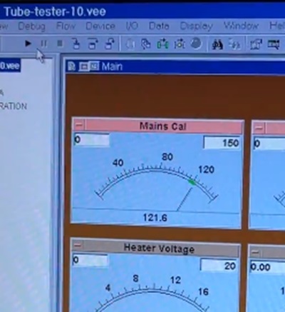 So before you begin a test, you need to do the mains calibration. For this, I picked the DC voltage across C8/C18. These are found on the electrolytic capacitor assembly. Careful! These have -320V on the outside cup, and this cup is not isolated. I added tape around those capacitors. It felt not very nice to touch -320V. With just a few screws you can detach the unit, and connect a wire to C8, tapping the -320V. This goes into one of the attenuators, so at the other end comes out -32V, which goes directly to the D-Connector. WIth just a few lines of code in VEE; this signal can be displayed as a 150V Panel meter. So now -32V needs to be at the +120V Mark, same as when calibrating the tester. This means I need to multiply this .-2V by a factor -3,75 in software, and the virtual meter in my PC Screen will indicate a 120V. Same as when doing a mains calibration on the L3-3 itself, it must be on "120" as well. The factor -3,75 must be adapted in the software, so it indicates on the PC screen the same value as the L3-3 hardware panel meter. You can call this calibration of the software.
Next step will be to show the internal 250V.