L3-3 tube tester. Test Button reversal
This is the "simple" Version, easy to do, in just half an hour work. A more complex version is, to add a relay PCB, but that is another project, which I only would advise if you understand the meter part of the schematic fully.
The concept of the L3-3 is, to show the heater voltage if no test button is pressed. So to see any test result, you always need to press the "Test" button. If you work with the L3-3 for longer than 30 minutes, you get a blister on your thumb, because the button is so heavy. Besides you have one hand less, because you always have your thumb on that "test" button. This was for me an important shortcoming. I found out, with some small modification on the switch, you can solve this problem.
To remove the switch from the top, you need a special tool, or as I did it, I grinded an old screw driver to fit exactly one of the two slots. Then, with the screwdriver in only one of the two slots, you can rotate the screw, and remove that funny screw easily.
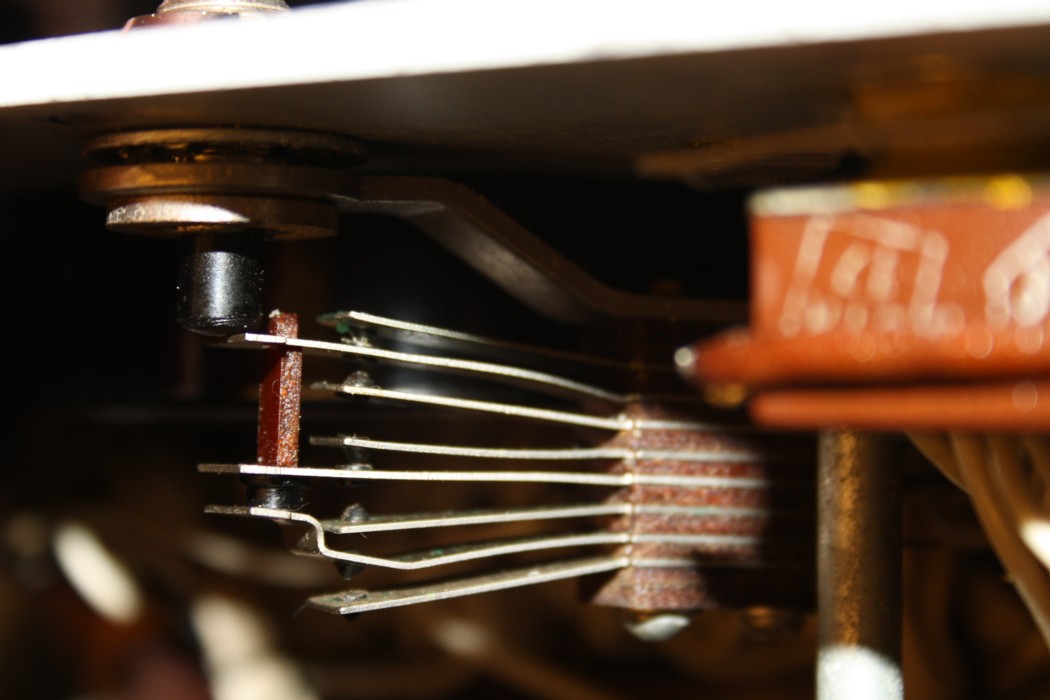
BEFORE
Mark the blades well.
When you take apart the switch, you must be careful it doesn't fall apart, or you will have a hard time getting the switch back together as it was. I would say it is very wise to write a fat stripe on the side, with a marker pen. Also make a few clear pictures. You could also mark the blades with one dot, two dots, three dots etc. It may be a good idea to tape the first SIX blades together a little bit too, since these stay as they are. Anyway make sure no "accident" happens,
Now, the work to do is very little.
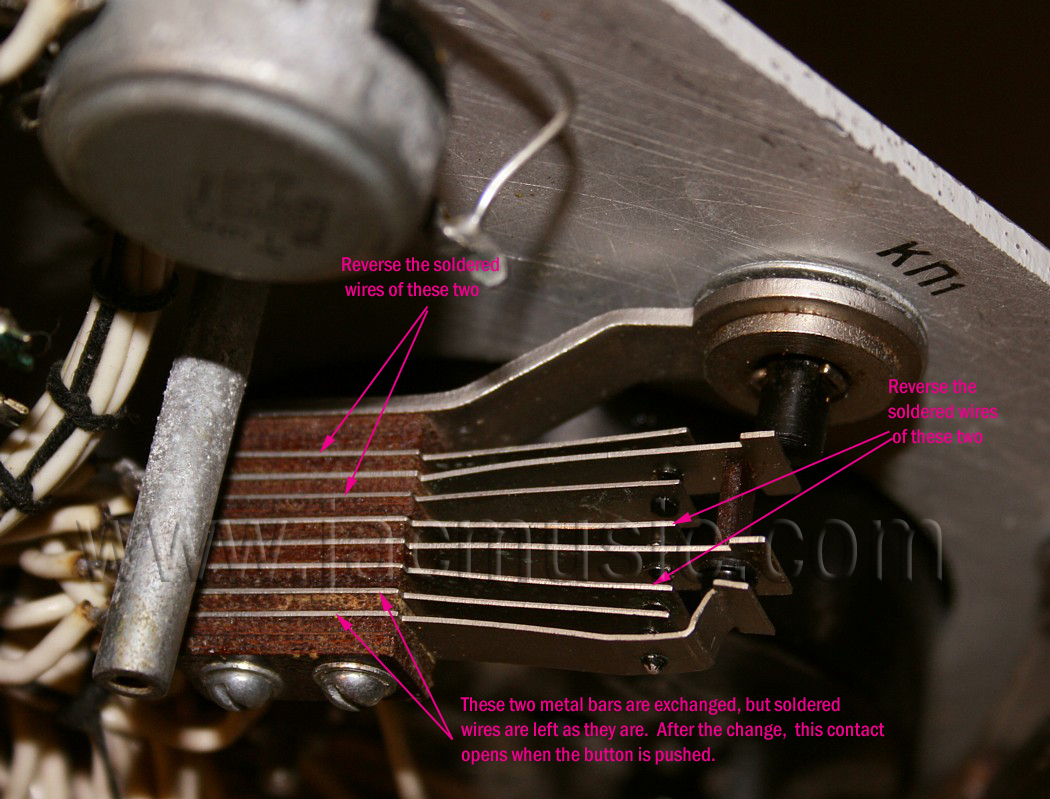
1) You have to remove the last two blades, these are the bottom ones (7+8) in this picture, but you leave the soldered wires on. The blades stay in the same position, so they are not rotated or anything. It is just you swap them, and leave the wires on. After this, you mound back together the switch, and this part is done. Remove the tape.
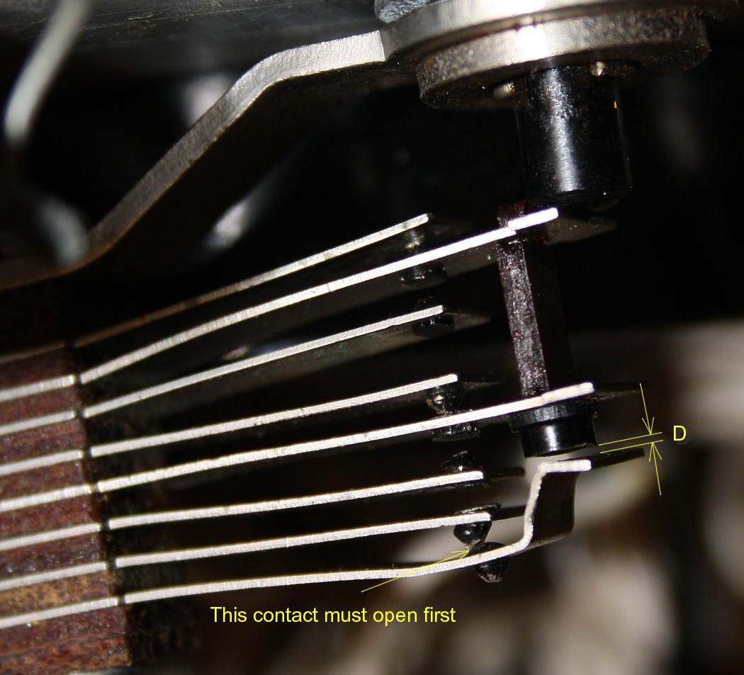
2) Now the blade with the bended end is at the last position. First thing you do now, is preliminary change the shape of the last blade, until it functions normal. After this you are note done yet. Now you have to check that bladed 1...6 open and close nicely as they did before. Un tighten the screws a tiny bit, and try to see what rotating them does. Do NOT re-bend the blades 1...6, since this is already nicely factory adjusted. It is just their position by rotating them, that you need to re adjust, so the silver contacts nicely touch each other in the middle.
3) Now comes the adjustment of blades 7+8. This is the "final" meter switch. If you press the button, first thing that must happen, THIS switch opens. (Whereas originally it was such that LAST thing that happens, this contact closes). This is important to do right. So you need to adjust the shape of the blades 7+8 accordingly. Basically this is done, by making the distance "D" in the last picture quite small.
4) Final control:
When you press the switch, FIRST 7+8 open, and after that the blades 1..6 do their function.
5) Now you solder off, counted from the top to the bottom: wire 1 and 3, and solder them back on, reversed. MARK them before you start! If you make a mistake, it will drive you crazy. Then the same is done with wires 4 and 6, and your 're done.
6) Tighten the screws finally, and re-check if all contacts are nicely in the middle, and open and close nicely as they should. Mount back in the switch and you're finished
AFTER. How to "TEST" button was reversed.
Detail of modified switch