Kalibr L3-3 Tube tester Audio board overhaul
Description
The Audio board has the delicate circuits on it. That is the oscillator, the band pass filter, and the uA Meter.

Audio Board of Mark Michalzik
Some older versions are hand wired, and they are a lot more difficult to overhaul. When you have like most owners, the PCB version, working on it is really easy. There is no real need to overhaul the sound board, and even when some capacitors and parts are not 100% any more, it works still, and can be calibrated also. It is just stability of the calibration can be greatly improved. With this I mean the three potentiometers in the face plate, for transconductance and leakage, which are used to do a quick calibration before you begin testing. However this calibration drifts often away after just a few minutes, and this just won't stop. With some testers it is not much of a problem, with my testers it was. Or perhaps I had the problem only in my head, but I really wanted a situation where I calibrate it once, and then don't need to do it again every 10 minutes.
12 years ago, I spend three months of email communication with Marc Michalzik, an extremely knowledgeable person, who does not avoid any project whatsoever. He had the same issue, and we both were determined to find the cause. But admitted, we did not find the problem cause at that time. I think now, I have found the reason, by coincidence. It was leakage at some points at the PCB, leakage at the flip switches, temperature drift of the potmeters, and some other weird effects in the Giga Ohm range. I solved it by doing all these things at the same time.
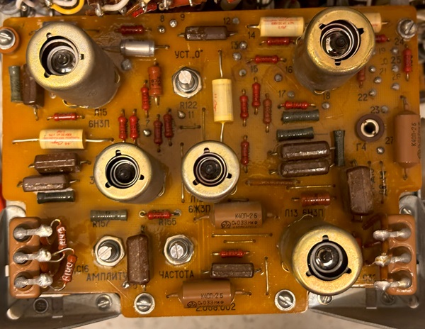
my Audio board of L3-3. Most parts have data code 1975
The board is easy to remove, but you do need to add number tags to the wires, and make a good sketch of where the wires were attached. The solder pads for the wires have some metal rings riveted into the PCB, so you can't damage the pads by desoldering. The PCB itself, though old fashioned, is good quality, and it was also lacquered at both side. The design was obviously hand made with those tape rolls, used in those days. But fair enough it was done well, except from a small error at the Potmeters, which they patched not extremely good, with filling rings. (More about this later)
First let me say, the old parts are good quality, but 50 years is a long time. All resistors were fine. The mica capacitors, no surprise, were all testing as new. They are capsulated into Bakelite, which is known to be one of the finest long term stabile materials. The light brown capacitors are sealed type MKP, and some of them were still good, and I left them in. I tested all capacitors for leakage at the rated voltage. Fives pieces however showed a tiny bit of leakage, and just to be sure I I replaced them by sealed versions as well. Marc send me a pair of Schottky Diodes, which we used to replace the old Germanium point contact diodes, but that did not make any difference. I probably will put back in the Germanium diodes later. This was all done 12 years ago, but no it did not improve the board stability, not even a tiny bit. Well, the cause must be somewhere else, but I stopped the project.
Now, in 2024 I picked it up again.
Possible reasons are:
- The flip switches in the deck plate
- The potentiometers
- The wiring
- The PCB itself
I just did all four of those, and.... voila: The stability problem was solved.
- The flip switches in the deck plate are obviously mains voltage switches, and the plastics looked smeared and dirty. So to prevent any kind of leakage problems, I replaced those with very good quality switches, with gold contacts inside. Also I used push buttons instead of switches, which solved what I call a small design problem. So now, with push buttons, I can not leave them set at 'calibration' any more, by mistake. (Which is really nasty if you don't see that)
- The potentiometers, are not bad by itself, They are closed types, no dust comes inside, they have a triple contact inside, and very good bearings. BUT.... they are carbon types, which means they have temperature drift, and also they change their value if the carbon absorbs humidity. This humidity goes away after hours or days of warm up time, and the value changes. But then, if the equipment is switched off, they re-absorb the humidity again after a few days or weeks. With historic carbon resistors you can see the same thing, value is never the same. I replaced them by 10-turn wire wound pot meters. The wire has little temperature drift, and no humidity effect. Each and every one I replaced, was an improvement. To make things easier for yourself, measure the value of them, after taking them out, and do not turn them. That way, you can replicate the value om the new potentiometers, so you don't get stuck in calibration routine. That way, the board worked instantly.
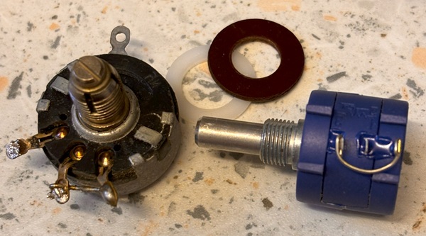 The picture shows how to wire them, so they rotate in the same direction.
 - The wiring. At some places the isolation sleeves are used. These have become smeared, and that will get worse in the years to come. They have already now leakage in the Giga Ohms range. Make sure they don't touch anything, and replace them when the touching is unavoidable.
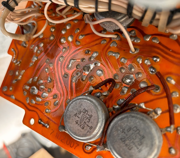
- The PCB has a small error. There are tracks under the potentiometers, which should not have been done, and they prevented a short, by using a pertinax ring underneath. This material can become leaky after decades. The new potentiometers have the axis isolated anyway, but I added a nylon ring in addition.
The sleeves are not so good any more
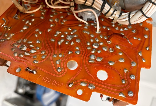
PCB tracks directly under the (metal) Pot meters. Not a good idea.
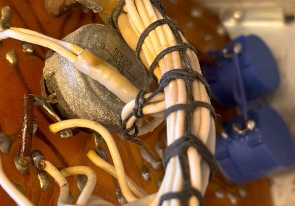
While everything was apart, I also exchanged the uA Potmeter. Look above how dirty it has become, you should not use this any more, to calibrate the offset of a 30uA meter.
RESULT: After all, I can not really say, which measure gave me the break through result, but all of these together made my L3-3 stabile, right after the tubes have warmed up.
,