Adjustable Bias Cards for L1 and L3 tester
The function of Adjustable Bias Cards
Of course, using adjustable bias cards is more interesting than auto bias cards, and it makes fun, because you can do things yourself. However, there is great misunderstanding with this test method about the practical use.
The use for such cards is NOT, to find out if the tube emission is still good. Believe it or not, but for that purpose, Emission Testers (or here, Emission cards) have to be used. There is almost no datasheet, saying you have to use Adjustable Bias settings to test the tube. These are extremely rare cases, and all other tubes have to be tested auto bias.
Adjustable Bias Cards However, are very nice when you want to CHANGE the bias during testing and see what that does to the transconductance. Because the RELATION between plate current and transconductance tells very much about the use condition. The idea is, to adjust the bias current to the ideal (average, or Bogey) value, regardless of what grid voltage that needs. Then, in that condition read if Gm is good. The more below average, the more use the tube has seen.
Sometimes people object, it is not right to force the tube in some bias condition it does not take by itself. This is true! But what bias condition is the tube taking then by itself? Is that with fixed grid voltage? No of course not, because that forces the tube always in a fixed condition. So that is a contradiction.
Normal for a tube is to use it in auto bias. Such an Auto bias test is also harder,because first you expect the tube to bias good in a real circuit. Will it do so? And then, if yes, it must give the right transconductance. Will it do so? More about this is written in the Auto Bias section.
Why it is wrong to set the tube to average grid voltage.
When using auto bias cards, people would automatically look in the datasheet, and pick the average grid voltage from there, and test the tubes like that. But we need to understand, what are we getting then? The result is not how strong, or how new it is, but only how much this tube deviates from average. Of course much used tubes are always below average, but out of the box tubes may sure be below average and are perfect quality still. For new tubes, such deviation is caused by plate distance tolerance, and not by a weak cathode.
So paying extra money for 'ideal testing' tubes, is not always needed. Even so, tubes that are above average need to be checked better WHY that is. If such tubes were 'better' by definition, then why did the manufacturers not make all tubes like that?
You have to accept tubes are not born all with the same plate current reading. If a tube has a higher value to begin with, it has not much to say, as it will degrade faster than such that were born with a lower value. In the end, lifetime will be the same.
There is an interesting observation
When plate current is below average, the transconductance is above average, and vice versa. This is of course a nice field for adjustable testing.
Warm up speed.
What can pay off, stick a cold tube into a pre-set L3-3 and watch the speed at which Ia rises. For used tubes that takes longer than for unused tubes. Compare this with identical brand tubes. This will give more and larger variations with adjustable bias testing. The tube under test must first be set for average current in hot condition. Then pull it out, wait until it is cold, and put it back in. The time in seconds, to needed to achieve 90% the original value is very good to compare new tubes with uses tubes. Also this is a very nice field for adjustable bias testing.
General Test with adjustable bias card.
- Test the tube at first with fixed grid voltage, as on the test card, and check if the plate current is in the green.
- Set it to the 'ideal' plate current now
- Test if transconductance is in the green. (otherwise you already HAVE a failure now)
- Go back to plate current test, but now set the tube for maximum dissipation. If not possible take at least what the test card allows you, you can increase the dissipation usually very much by increasing the anode voltage.
- At highest allowed dissipation check for leakage and grid current. (Click those links, these are two test sequences)
- If the tube fails at any of the above points, trouble is expected soon, even when it works still
Will the tube be improved by burn in?
Perhaps yes! For this use the Auto Bias cards. Burning in with adjustable bias cards may lead to tube defects, due to thermal run away, or due to the tube improving very much. This may over heat the tube unexpectedly, at a moment you do not see it, and then it self destroys.
Errorz and Misstakes:
This would be the wrong way to test: You take the 300B datasheet, and you will see in there: 300V / 60mA at -58V Grid. Transconductance 5600. You set the card for -58V Grid, and you test the plate current. Suppose it reads 49mA . (not 60mA.) This can be normal factory variation, just caused by smallest differences in anode distance. Now you measure transconductance, and you find not 5600 but 5000, which is only 85% of that.
The (wrong....!!!) result would be:
Plate current 82%, transconductance 85%.
It gets really silly if the test person calls the plate current 'Emission', (or even 'Emissions' suggesting more than one emission), and then we get:
Emission 82%, transconductance 85%. The expensive Amplitrex AT1000 expresses it in this totally confused way.
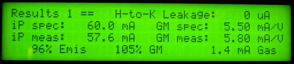
Silly example of wrong interpretation by Amplitrex AT1000. Suggesting Emission of this tube is 96%
On the other hand, you can make a nice buy on Ebay when you see the seller make this mistake, and there will be not much bidders for such a tube with emission below 100%.
Here is how to do it the right way: You take the 300B datasheet, (or our test card) and you will see in there: '300B tube... 300V / 60mA at -58V Grid voltage. Transconductance 5600'. As a first result you see indeed 49mA. The first conclusion is the tube is good, because that's in the green. Now you want to know: how good?. For that, you adjust the grid voltage such that the plate current becomes 60mA. Now, you measure the transconductance, and here comes the surprise: It is 6100.
The (correct....!!!) result for exactly the same tube would be:
Plate current 82%, transconductance 109%
For specialists: Why does one parameter go up and the other goes down? With this tube, it can be concluded this tube has some tolerance of plate-to-grid distance. If that distance is larger, there will be less anode field gradient. (less Volt per Meter) So you can also say AC feedback is lower, as the anode AC signal field is in opposite phase to the grid signal field, and these fields add up. This lower feedback will make Gm rise. That was for AC. For DC, is another situation. The anode is further away, and the negative DC voltage on the grid will be less affected by the Anode voltage. (Those two fields simply add up, also for the path from grid to cathode). So the electron-stopping effect of the grid will become better, and less anode current will flow. So, lower plate current, combined with higher Gm, is nothing but anode geometry, and is not caused by quality of the cathode.
CONCLUSION: Adjustable grid voltage is testing is easy to do, but results are difficult and misleading. This method is not supported by any datasheet It can be used nicely for matching, and other way of finding out tube data. It should not be used to say something about tube quality or cathode quality. Instructions in many datasheets is found However, for auto bias testing.