Max Grundig Tubatest2
This is a repair report about a Tubatest2
 |

Picture: First business activity of Max Grundig, with his partner Karl Wurzer in 1930, who was only involved financially. Opening of the first shop
Grundig's company rise and fall was impressive, and their end came when they went for the wrong video recorder standard. They never got over that, and Max Grundig died in that period. His very young wife had to clean up the mess, and she had to managed suddenly this large company from one day to the other. She took several wise decisions, and perhaps Max should have let her do so before. She was able to save some parts, but it was little compare to what it once was.
Officially the company still exists, but is is only a brand, which is the hands of marketing people, selling products with 'Grundig' printed on it.
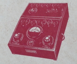 This tester has quite a story attached to it. I bought it some 15 years ago, I knew not much about it, and it was sold in unknown condition and small cost. So I gave it a try. What I got sparked my interest a little bit for the Grundig company, which ups and downs are a very story of this single person, building an empire, one of the largest Electronics companies in Germany, and the way down until nothing was left, as what could be saved by his wife.
The Tubatest is a so called emission tester, but it is a real one. So not one of those fraud testers that people pay 200...300 for in Ebay, and are completely useless. This tester was designed by Max Grundig himself, as his first project after the war, as he went back into civil production again. His work during the war, was repairing and producing military equipment for Hitler's army, and he has quite a reputation as genius engineer. Add to this 5 years repair experience during the war, and I would say, this man knows what a tube tester has to do. This tester here is the last and largest of it's kind.
 This is an emission tester, and it begins a test with a short and leakage test. For that they use an interesting switch, which first measures leakage between the cathode and Grid1. For this the neon lamp if the meter is used. The lamps is also used for initial test of the heater wire. So quite similar like the one-knob method of the Funke Testers are doing it, and probably this inspired him. Though switch quality of the Funke is a bit poor. I guess that inspired Mr. Grundig also, and he made the switches in top quality. After Grid 1 is free of leakage, you rotate the know 1 setting further, and Grid 1+2 are tested together against the cathode, then the next electrode, etc until in the end all electrodes are inter connected, and now the whole tube becomes a device with only two connections, an it is a diode. This diode is used in a rectifier circuit, and produces a voltage over an hand made load resistor, which was calibrated at 720 Ohms in this tester. I know it was that value because the tester was never opened before. In series with this resistor is 60 Ohms, which acts as current sensor. So 50mA gives 3 Volts DC.
the Variable Resistor is the load, and the current is read by the meter. So the whole logic is simply when you know the setting which produces a reading "good" for a new tube, any weak tube will read accordingly lower. .
 The original manual was with it, in collectors condition. There was a name stamp on it from a radio shop, and my impression is, this was the first owner. I had no time too look at it, but I did so 15 years later. Searching for that shop name, I found pictures of the empty shop in the internet, and also a radio collectors museum who wrote they received large inventory of old documentation and items from the Gruler family, after the owner of the Radio shop has died. So I was the one who bought Mr. Gruler's tube tester, but I don't know if it was from the museum or the Gruler family. Very probably from the family, because it was not working, but also never opened before. Whereas museum people would have looked inside first, and probably have kept it also.

After opening the tester, it was like a time capsule. It was simply never worked on, and the main defects were a damaged switch and a sticky meter. All metal foil resistors were still good. No carbon resistors were used. The wire adjustment resistor for the tester calibration was falling apart, but the wire was still good, and I could repair it nicely, even set it at the same resistance, because I measured it before. The calibration looks good. A new 6L6 reads nicely in the green.

There is a youtube video from somebody else, and it shows the same reading for a 6L6 as my tester. I have used it on a 220 Volt transformer for the calibration, because the mains transformer has only 220V and 240V.
 Inside was a loose paper flying around, saying it was manufactured April 1946. So 72 years ago. You have to understand that date. In 1946, Germany was occupied by the Americans, and Max Grundig was forbidden until further notice, to manufacture radios as he intended, because he had employed 150 deported women from Ukraine, working on parts for secret weapons. During his work for the Hitler regime, Max Grundig learned a lot about military equipment. So he said, ok if I am not allowed to produce radios, perhaps I can produce tube testers? And they let him do that. Some years after, he was allowed to start a radio factory, and he dropped the tube tester line. So Tubatest 2 was the last one he made.
I was surprized by the genuine quality of the wires and isolation materials. It was all still soft, and undamaged, I could leave that all as is. It looks like any normal plastic wire. The switches are over engineered quality, the metals of the contacts is solid silver alloy , and you can take them all apart until the last piece.
 I soon found out the reason why the tester was taken out of use. The heater switch was damaged. The fingers had scratched too deep inside the contacts, and it worked unreliable. Much to my surprise, the contacts were made of solid silver alloy, and quite thick also. The switch could be taken totally apart, and could be flattened with abrasive paper on a glass plate.
 Here you see the same switch after repair.
The work which needed to be done, was cleaning of the switches, resolder (all!) joints, fully restore the panel meter, with a new scale, and some small repair of wood cracks. It is in perfect condition again. This tester works very reliable and is able to do a few modern tubes, meaning you have the settings. All that is missing os the setting of the "R" pot meter. (The load). For this you would only need a new tube, and check what R-Setting makes the meter show "good" reading. It's as easy as that. There is already a setting for the 6L6 in the original book. That works fine. If you put in a KT88 you will notice it reads too high. So all you need to do, is adjust the R-Setting until it reads the same as the 6L6, and write down that number somewhere. And that is all you need to test KT88.


The meter itself is very good quality. A very big Bakelite case, and it is obviously specially made for Grundig, with the lamp and the viewing hole in the middle. It had no rust, no damage, and nobody had opended it before. Just the glass was a tiny bit loose, and also the lamp part was loose, so some dirt came in, and damaged the face plate.

To me it looked like the lamp assembly was not build dust proof from the beginning. But it is now. The magnet and moving coil were all ok. So I decided to restore it, using the later version of the scale, with coloring on it. I think I found a nice letter type, looking the same as original.

If you take the trouble to find out the settings. It even has original settings for 6L6. Which you can also use for KT88. I have drawn the schematic with new software, and then it became clear how it worked. The method for testing for shorts and leaks is clever and interesting. And most of all it works.  We get the same situation as always.If I put am RE84 radio tube from the 1930's on the tester, it will for instance say, it is 'weak but just ok' So I know that. Then I can put it on a curve tracer and get the curves, which tell me nothing. I can test transconductance which is 25% lower. All of that tells you nothing. But this tester, primarily made for such tubes, says it's 'just ok'.... I trust it.
The transformer can be set for 110V or 220V by resolder a wire from a tap.
Accuracy: I tested some tubes on it, and it works very good. Please note, that was after all work I did, but before that it already worked too. Just it worked not very good, due to bad contacts and switch problems here and there.
It is hard to attach a numeric result to something like 'good-bad' but I had some used tubes on it, and they came out as they should. I put an General Electric NOS 6L6 on it, which I use for reference, and is known to be full perfect. The readings with that tube was: 120% with the mains exactly on 110V / And the tap on 110V of course. Drop at the leakage test was only 0.5% on all electrodes, so the tube is testing indeed near perfect.
Here is a short version of the operating instructions:
- Turn both big switches (left and right) counter clock wise
- Do the settings by the book, that is R for the load, the K-Pin(s) for the Cathode (Kathode in German), and the E-Pins for the Electrodes.
- Set the selector on the top box when a socket from there is used.
- Test for Cathode-Heater leakage, with the left switch on "K". Good=Lamp off
- Test for Filament continuity with the left switch on "E". Good=Lamp on
- Now the testing can begin. Set the heater voltage with the left switch
- Set the right switch to "1" to test quality on the red-green scale.
- Now comes electrode leakage test. For this, first adjust the meter for a reading of 100% with the "R" knob while the setting of the right switch is still at 1.
- Rotate right switch through positions 2...6. If there is leakage, the readings will be lower than 100%. A maximum drop of +/-15% is allowed.
- End of test instructions
Note this:
On the right switch with my tester is written "kOhms" but this was obviously intented for another purpose, I do not know this purpose, but sure the switch has nothing to do with "kOhms". You can click on this picture for a full version. Read our copyright infringement notes.

Clicke here for the second part of the schematic ( The top Box). This in uncomplete, but it is good enough as it is.