Since 1993 Copyright Notice
Fake Precision with instruments
The fine scale trick always works
This trick is an old one, but a good one. Designers of equipment make great use of it. I found it even in a new made, digital tube tester called AT1000 by Amplitrex.
Don't be misguided by nice scales with fine stripes, or a king size panel meter pretending to do a magnificent job. Also don't be misguided by digital numbers with many digits, which is the today's digital bullshit version of the same. This is fake, because this suggests 0.5% accurance, and the whole tester is not better than 15%. In the next meter, by ELPO they don't fool the owner with that.
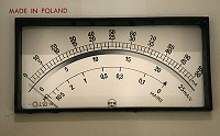 The tiny little meter on am ELPO 508 tester is better than almost any other, because it's a tout band meter, which has no friction. Just tiny, and it fits perfectly in the small space they had left for it. NOT suggesting any fake precision with fine scale divisions, which frankly this tester doesn't have anyway. On purpose, you can see the 100mA Scale makes steps of 2mA, not trying to suggest anything the tester ITSELF can not do.
Look at the thermometer picture, for some basic understanding of how fine scales work.
This is actually very interesting, and when I did my studies, during lab hours we were taught understanding of the difference between what you initially 'think' you read, and what it is guaranteed to be said by the meter. My lab teacher was sort of specialised on that, and it was really interesting to get more awareness of how measurements have to be done. Also you he showed us the delicate fooling of the user, by many instruments, on the edge of being legal.
Here is something essentially with all meter readings, digital or analog.
Question: When you get presented by a meter, a number "3", what does an HONEST meter, and a similar equipment designer want to tell us?
Answer: It means the measured result was closer to 3, as is was to 2 or 4. Very simple. So 3 means not 3. 0. and 3.0 means not 3. Because when a meter says 3.0 is means to say the result was closer to 3.0 as it was to 3.1 or 2.9. When you design equipment, you can print this sentence and hang it above your bed, because it is the most essential thing when creating a meter scale, and it is forgotten almost always, like a matter of principle.
So, let's do the exercise with these identical thermometers at the left.
For the product definition, in the middle is what we call the SYSTEM it is the blue bar which moves. The numbers are the SCALE. So there is the SYSTEM and the SCALE. Now, two things create the reading error. First, the system has a measurement error, and second, the scale has a reading error. These two meters pictured, are two out of the same production batch, and were used under the same circumstances. Yet each of them is not defective and can be sold as good working, for PRIVATE purposes only.
For trading purposes, it is illegal to sell fake precision. Even when you don't fool the buyer. So when the butcher uses a weighing scale, saying 999 grams, it may not be 998 grams. If so, the weighing scale is defective, and self tests routines must at least TRY to find this. (I can tell you, I was in this work, long ago, designing hardware and writing test software for this)
So when a digital instrument for trading purposes is generating a reading with a 10% accuracy SYSTEM that is not illegal by itself. But it means when presenting a READING in between 0 and 100 kilograms, it must do so in steps of 10. So when the software finds the weight is "20.231" it knows by itself it has 10% error. So it may as well have been 22 or 18. Which can not be displayed even on a two number scale. What two digit number could represent this? Try it, It is impossible. So the READING must show 2 and the unit is 10 kilograms. So only a one digit reading is allowed. So the plain fact that you can see the reading change like 1, 2, 3... makes it impossible to read 20.231. Which last number may seem more interesting to know, but it is not. Reason is, the number is wrong anyway, because it's 10% off. So in case the instrument must display 20.1, 20.2, 20.3 etc, the designer must use a 1% System. And not fake the user with a 10% system. To make fraud harder with trade purposes, digital systems must internally work with one digit more as the reading. (and be able to show this during calibration). But for scientific purposes this is not required. Even so, they can do the opposite, and generate an extra digit by averaging 10 or more readings, but at some point this enters the zone where they begin to fool the user. Let me explain this, and I can tell you it is done. Suppose you have a fake 4-digit voltmeter. The internal software is only 3 digits. Internally, the software would produce (let's say) 10 readings per second, and updated the display 2x per second with the average of 5 readings. Like this, when 8.120000 Volt is applied with an 8 digit precision source :
Seconds |
Real time |
Update |
0 |
8.11 |
- |
0.1 |
8.12 |
- |
| 0.2 |
8.13 |
- |
| 0.3 |
8.11 |
- |
| 0.4 |
8.16 |
8.126 |
| 0.5 |
8.13 |
- |
| 0.6 |
8.18 |
- |
| 0.7 |
8.12 |
- |
| 0.8 |
8.01 |
- |
| 0.9 |
8.13 |
8.114 |
1 |
8.01 |
- |
So that you understand the point, for trading pupose, the above meter may only show two digits, so must say: 8.1 and no more. For hobby purposes it may write 8.12, but write 8.126 is a fake precision. However this is very difficult to prove.
Conclusion: There is no point in making the scale higher resolution that the inner system. In a way, you are doing the same, when you over-calibrate a tube tester, which is sometimes so hard to explain why this is not working well.
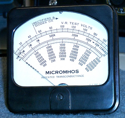
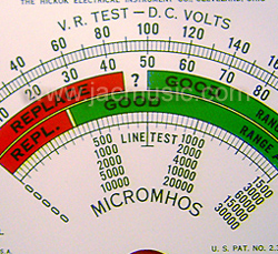 Meters like the later Hickoks use ultra thin hair stripes with a much finer resolution that the whole tester can ever have. The meter shown here is not even so bad, there are much worse examples. You read something 'very' precise from a fine scale, dividing the 1500 Mmho range in steps of 25Mmho. (this is so crazy.... 25Mmho on a 5% error tester). So the difference is indicated between 1475 and 1500 Mmho. This can never be so because the whole tester had 5% deviation at it's best when it was new. (At this scale 5% is 75 Mmho). Well and some are even 15% and they use the same meter. Did they know this at Hickok? Well of course they did! The older Hickoks like I-177 do not suggest a higher accuracy as it actually has. You can read the Gm scale only very roughly, which more represents what the tester is actually doing. And nooo... If you think now the I-177 is imprecise, you completely missed the point. It has the same precision as any other tester. Just be aware that the later models with the very fine hair stripes are also 15% precision testers, and you can't change that by using hair stripes of 1% resolution.
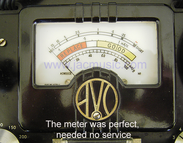 The early AVO VALVE TESTER has the 'very fine scale' trick also, they really were overdoing that. With the later models Mk1...4, CT160,. VCM163, the designers at AVO have come with their feet back on the ground. With CT160 which is the most precise of all AVO's, the lower scale has numbers like 20-40-60-80-100 and divides the range from 80....100 only with five stripes. This is true honesty, because indeed by no means the whole tester can't do any better than that. The mega Ohm scale jumps from 10Meg to 25Meg. It just tells you in between you can estimate the number yourself, but the tester cannot, which is true. All it will tell you the resistance is in between 10 and 25 Megs, and if closer to the one or to the other number. Keep in mind measuring 25 Mega Ohms is not easy without electronics. However, at lower resistance it gets better, being able to measure with 50x more accuracy (200k) . Mmm still a lot of deviation. Is that meter not good? Oh yes it is! It tells the truth about the measurement. So when I measure 5250 Mmho with accuracy of 500Mmho, I believe this. I love my CT160. When I measure 5250 Mmho in a Hickok with a suggested meter precision of 25Mmho, that 25Mmho resolution is bullsh.... I don't believe it at all. I never use a Hickok for precision measurements, but it must be said the red-green scale works perfect, perhaps the best of all testers. When talking about accuracy, the red/green scale had only 'red', 'green' and 'white' in-between. Well fair enough, and that's what you're getting.
 For our German readers, or those who want to give it a try. The FUNKE W18 manual gives really good information about tube testing in general. (Ab Funke seite 11 lesen, =Pdf Seite 8)
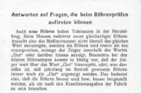
As you can understand I wanted to know how good the accuracy of the W19 is, because I had fully restored it.
 Very much information about it you will find on the main page, including a full restoration report, and meter calibration. Just as a fun project, I re-build this one to the best accuracy I could get. The little digital meter you see here, is just for the pictures, but it happens to be a good one. Actual restoration has been done with a new Agilent digital meter, which is not on the picture. Very well done with the Funke is the voltmeter option, since that very quickly tells you something about the panel meter (after all those years). Note old panel meters often show a few % less, due to the magnet loosing it's magnetization. With all old tube testers, you have to begin with calibrating the meter, and get readings + impedance back to what it should be. This is a rock-solid, feet on the ground, correct and honest tester. Well worth the +1000 Euro price they go for.
Actually the one I have is now amazingly precise, and when I first saw the wooden inside construction, I did not expect this. I will explain in this text, where this precision results from, but it is mainly the well calibrated panel meter, and the very precise voltage stabilizer tube GR150-DA. So when you read 10mA it means 10.0 and not 10.1 with this tester. I do not know if all W19 were originally that precise when they were made 50 years ago, but mine is in this condition at least today.
When restoring anything like a multi meter, or a tube tester, with an analog panel meter, the meter itself is always not very good anymore. 50 years is jut too long time. Aging and users have usually done their work, so usually there are errors like:
- Rust in the magnet gap, sticky meter
- Partially loose glass (dust comes in)
- Friction of the coil bearings
- Linearity error due to coil deformation (by overload or drop)
- Full scale error due to loss of magnetism
- Needle balancing is bad (so reading changes at different angle
- Anti static treatment is gone
- With the Funke comes additionally the ladder network inside meter
- Amateur repairs attempts have gone wrong
- Try to change meter readings attempting to correct other errors.
So the standard work at the beginning of a repair is always remove the meter and test it separately on the bench.
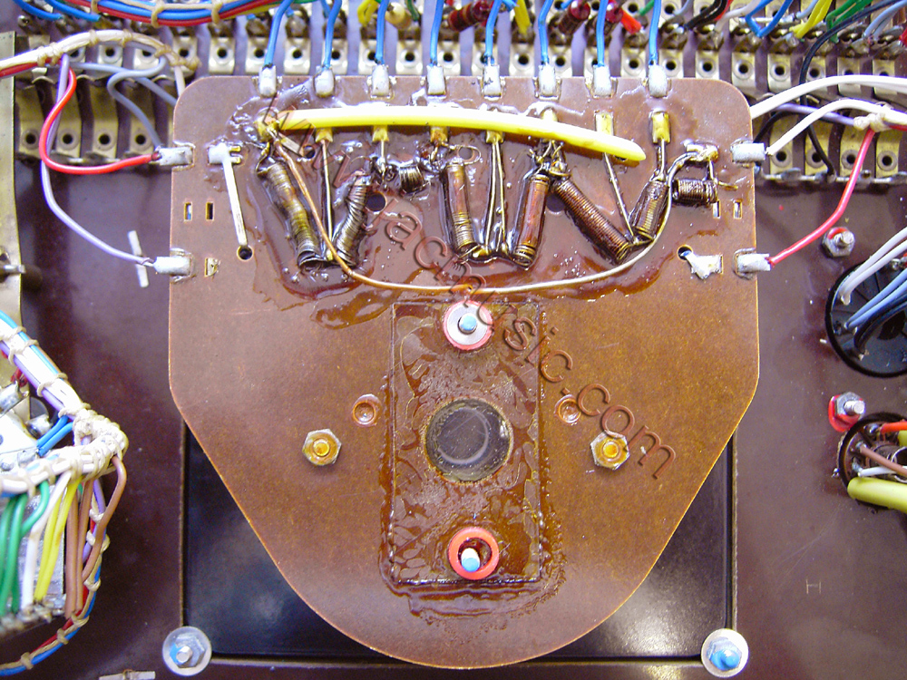
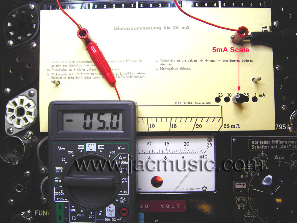
This is the meter with the cover plate removed. You can see the ladder network for the current ranges. In the middle you the hole through which the stabilizer tube lights through.
The stabilizer tube also act as 'on' lamp for the tester, but also shows the load of the power supply. The dimmer the lamp, the higher the current, and when the lamps is off, the power supply still works, but is overloaded or even shorted by the tube under test. Since the power supply uses a tube rectifier it is also current limited. I never tried, but at am overload, probably all you damage is AZ12 rectifier inside. All in all, a very clever method. To make this possible the stabilizer tube is a mesh type, so it burns amazingly bright, but obviously Funke took only advantage if this, and had them not specially made in mesh version just because of this. They did purchase However, a higher precision version. (So other designation GR-150 should not be used)
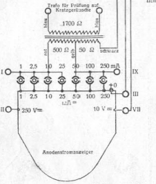 Originally the multi meter seemed not so good, and had errors of a few percent depending on what scale, and current range. I did not investigate exactly where the errors came from, but I took it completely apart, even the moving coil was removed to clean the bearings and the magnet. I do not recommend this to do yourself, as it is not really made to take it apart. I had to re-glue the glass from both sides too, and many small work. After this was done, I found out there quite some error in the ladder network. It may well be it was never calibrated any better. For calibration, they used wire wound resistors, of which they scratched off a thin layer with a knife. The scratchings were still visible, and after that it was lacquered. I found the same method of calibration in an AVO8 multimeter, and in my Tektronix 576 curve tracer, where they laser tuned the resistors of the ladder network, but not lacquered. then afterwards. So you see, even when the case of the W19 is of cheap wood, and the Tektronix 570 looks like a Rolls Royce inside, Max Funke to my opinion did a better job. Anyway, for the fun of it, I calibrated the ladder network better than 1%, by adding additional resistors in parallel, and then scrape off some more off the wire wound resistors, as needed. Nor forgetting to lacquer them afterwards with two components glue :)
Heater Voltage error.
This is a problem with almost every tube tester. Also W19 has too high voltage with tubes that draw very little current.
 You see here a TRUE RMS Voltmeter, and it measures 6.7 Volts heater voltage instead of 6.3 Volt, when testing an ECC88 tube. The heater voltage of this tester cannot be adjusted, so it is one winding for 60mA heaters, and 3Ampere heaters as well. When it gives 6.3 Volts at 3Ampere, then 'only' an increase to 6.7 Volts at very small current is not even bad. This is a good transformer. The problem with this however, weak tubes tend to give significant better readings at already 6% higher filament voltage as here. The effect is even more with DHT tubes. So an older DHT tube may easily read 10% better than it is. As long as you know this, you know what you're doing, but... there is a very elegant way to correct this. For this, please read the following part about mains voltage.
A much bigger error with heater voltage comes from leaving the mains voltage tap to 220V as it was done in 1950 and forget about it ever since. But we have 230V already since decades already now. So to save the whole tester, I set it OF COURSE to 240V. This drops the heater voltage accordingly, and with my W19 I took this choice, so to make sure the smaller tubes are tested with more accurate heater voltage. Beware for any tested to be 'good' tubes on Ebay, with a W19, because changes somebody has still set the internal tap to 220V is the highest. Most users do not even know this makes a difference.
A better way, would be to add a small 230V to 10V / 1Ampere transformer inside. The 10V winding is then serialized with the 230V mains, making it 240V. the tester at it's 240V setting is then connected to this new created 240V. Principle is the same as an auto transformer. So output power of this is 240Watt which is enough. I might do this one day.
 In the next picture, we repeat the Funke W19S measurement with the same ECC88, on a more versatile tester, the Russian L3-3. With the L3-3, you can perform any test you like, so imitating a W19 is very easy. We just set it the same as the Funke W19 card Nr 1088, which is for the ECC88, including the TOO HIGH filament voltage of 6.7V the W19S uses. The result is really as expected. You can see both testers show the same number: 10.0 mA very precise. At least this gives a very good feeling about the good function of each, and the good calibration.
 Let's go back now to the fact that we tested the tube at too high filament voltage of 6,7V. Look at the next picture, and we will re-test the same tube, but this time at the correct filament voltage of 6.3 Volts. You see this makes a certain difference.
Conclusion:
This tube measured 10mA on the Funke W19. When this test was repeated on the L3-3, with the correct filament voltage for this tube, it measured 9.5 mA instead of 10mA. So I do want to say, the current measurement and anode voltage is awfully precise, but differences with heater voltage compromise the result. This is However, the same problem with almost every tube tester. The ones I know that do not have this error, are AVO VCM 163, and the Russian Kalibr Tester L3.
How important is 5%? Here is a way to find out. Go to a supermarket, and put down 19 Euro for 20 Euro of goods. Tell the cashier, 5% is not important, and just walk out.