Electron Engine ™
Printed Circuit Boards by Emissionlabs
EE80 ventilation Adapter with status LEDs
AVAILABLE June 2024
The order number is for the PCB, with LEDs and SMD resistor.
Description
These EE80 air ventilation adapters are compatible with the Yamamoto sub plates. Outside dimensions, appearance and mounting is the same. We have one to replace the original Yamamoto 30mm sockets, and one which is 31mm, for some Chinese sockets. In addition we have a 27mm Version which fits some vintage sockets. All have 38.2mm screw hole distance.
In addition, two LEDs can be used. If the LEDs are not used, just do not mount them, and the sub plates will look the same as Yamamoto. At the back side of the sub plates is a small printed circuit board. Though it has little parts, it works precise, because the forward voltage of the red LED is used as a reference.
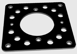
Air ventilation adapter without the LEDs mounted. Like this they are compatible to Yamamoto.
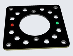
Air ventilation adapter with the status LEDs mounted.
The green LED works continuous, analog in pace with the plate current. Indicating the normal function. The Red "Alert" LED begins to burn very bright if the anode current exceeds the programmed value.
The "alert" limit can be set from 10mA to 300mA. The Board has 10x over capacity. So it is virtually impossible to damage it, because no tube can do 10x it's rated current.
The board has a ground plate, connected to the mounting holes and to the metal part of the tube socket. Like this the cage of the amplifier stays shielded against hum fields.
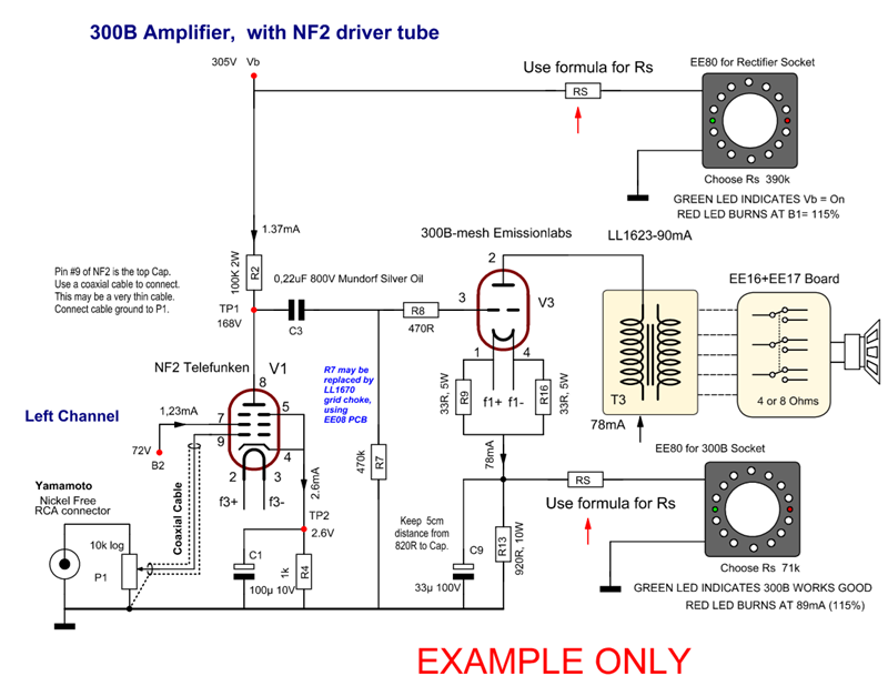
How to use it:
EE80 board can be used with a classical auto bias circuit, or can be used to warn for too high voltage of the power supply.
Here is how to connect the board. It senses the VOLTAGE across the cathode resistor, while current flows through the cathode resistor as normal. The programming resistor determines when the red LED begins to burn, and makes also the brightness of the green LED the same, for any cathode bias current. This simple, but effective circuit used the forward voltage of the red LED a a reference.
The programming resistor is calculated as follows:
Rs = Cathode resistor x (Cathode current -1mA) |
Calculation Example:
Cathode Resistor: 680 Ohms.
Tube current 50mA.
So we have to take the tube current, minus 1mA.
Rs = 680 * (50-1) = 680 * 49 = 33320. Choose: 33k
Possible range of use for Auto Bias tubes
- Tube current from 9...200mA.
- At Bias voltage below 15 Volt, the formula gets somewhat unprecise. That does not mean it does not work, you just need to find the best value of Rs experimental. The lowest limit is 9...10Volts.
- This circuit uses always 1mA DC current, regardless of the amplifier resistor or bias voltage. You can try it with the above example, bias voltage would be: 50mA*680Ohms=33Volt. Then, from 33Volt and Rs=33k, the circuit draws 1mA. This current adds up to the plate current. For larger tubes this is no issue, but for smaller tubes, you need to choose the plate current 1mA lower.
Monitor a power supply voltage
This is only possible when the chassis ground and power supply ground is the same, and when the EE80 is mounted on the metal of the chassis. In that case, the EE80 board can also be used to monitor the power supply voltage. Choose the series resistor Rs such that the green LED burns under correct conditions, while the red LED begins to burn if the power supply voltage becomes too high voltage. This may happen, in case of a output tube failure, or bias adjustment failure as well. In such a case, the electrolytic power supply capacitors could take damaged. So a continious monitoring is alway a good idea. With the use of the EE80 adapter it needs only one resistor.
Roughly for power supply use, Rs calculates as:
Rs = 1250x Power Supply voltage |
Calculation Example:
Power supply is 305V
Rs = 1250 x 305 = 381k / Choose 390k.
Rs Dissipation = 0.25Watt / Choose 1 Watt
To adjust it precisely, wait until the amplifier is all ready and finished. Then initially find a value for RS at which the red LED is just beginning to burn dim at normal condition. After this, use a Rs value which is 15% higher. Now, the red LED will be off, and the green LED will be on, showing the power supply voltage.
Available socket diameters:
Order nr: 321-027-17. EE80 for 27mm sockets,with smaller flange as normal. Such as the Ediswand NOS Loctal.
Order nr: 321-030-09. EE80 for 30mm sockets, STANDARD dimension.
Order nr: 321-031-84. EE80 for 31mm sockets, with wider flange as normal.
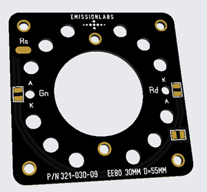
Back side. The series resistor Rs is connected, with one side to the Rs solder pad. The other side is connected to the auto bias resistor of the circuit.
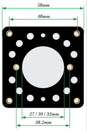
Dimensions are given here for three adapters. The flange is normally 30mm, but tube sockets also exist, which are somewhat smaller or wider.
Order nr: 321-027-17 (27mm)
Order nr: 321-030-09 (30mm)
Order nr: 321-031-84 (31mm)
Recommended chassis hole:
D=55mm